Website powered by

Houdini Blog #13: COP's

General / 27 May 2019


This week I went back on doing some research on patterns, more specifically with COP's. The video that inspired me is a talk by Simon Holmedal.

In that video around 28:30, he showed how COP's can be used to create patterns. A few post ago, post nr 9 I talk a bit about noise and patterns. I didn’t talk about COP's, because I didn’t know so much about it.

The main idea here is that COP's are used to generate a detailed pattern that can be used on the arm. For example on the part where there would be no cover on the arm and you can see through to the arm, there will be a detailed pattern.

Here is a demo of what it can do.


What is COP's?

You might have heard about COPS or used them now and then. But what does it stand for and what can you do with it. 

COP Stands for Compositing Operators, in here you can manipulate images. You can sort of see it as a rough version of Substance Designer.

You can create certain patterns/noises but you can also import textures and adjust them.

I have used COP’s before and that was to make a sprite sheet for explosions. It was really nice to use for that situation. For more info about making sprite sheets, see this tutorial.


Patterns in COP's

To create your own patterns I recommend to use VOP’s. In post Number 9 I showed some basic information about it. In COP there are not that many base noises and structures. You can also import a model and try getting the pattern of it, I have not research this but have seen it in a tutorial.

As example you can create a VOP COP generator. In here use an unified noise and change the type and the frequency. You can create a HDA from this and use it as a base noise generator.

Other VOP patterns

As you play around with the COP’s you might see some familiar nodes compare to Substance designer. COP offers similar blending modes like Designer but can some times be confusing to use.


Here is a simple example of how to create a pattern. Starting with the VOP COP (I made a HDA from it) and then using the dilate erode (I like this node). In here the dilate erode is used to get the black edges bigger and remove small islands. After that you can level it out and tile it.
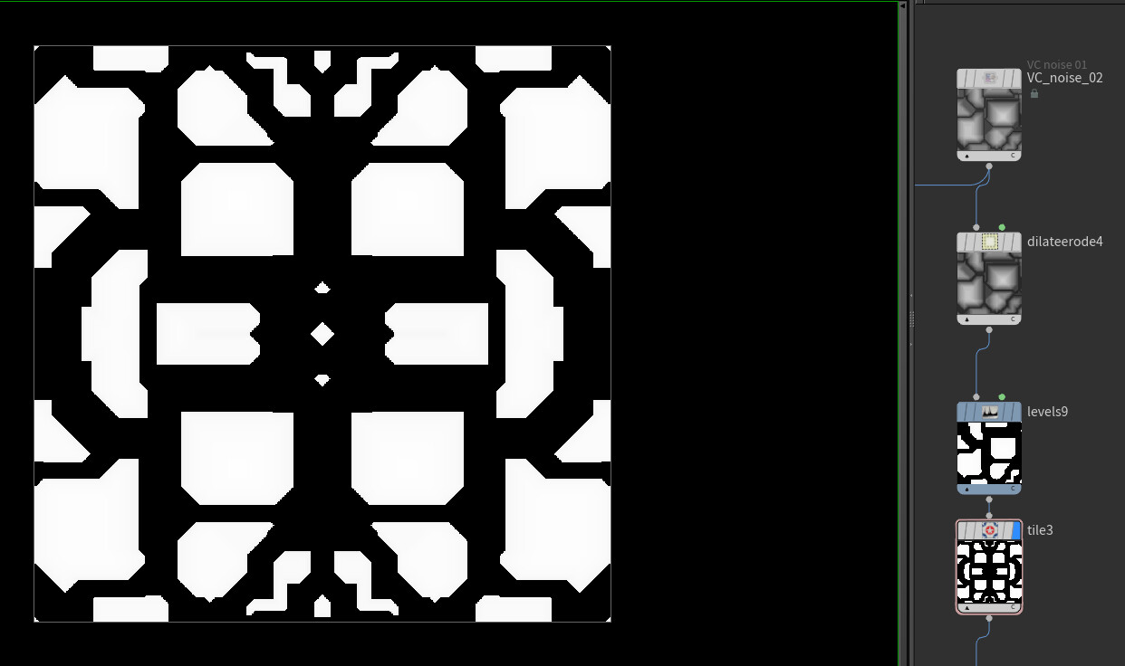
To make it more complex you can start layering noise and patterns on each other and then you will have a similar result as I have at the beginning of the post.

Now the question can be how do you view this in the viewport on a custom model. This can be done by an expression that can be used in a material or in quick shade sop. Of course you can also export the result to a texture and load in back in to Houdini.

`op:/obj/YOUR_MODEL/cop2net1/NAME_NODE_TO_VIEW


Using COP’s for patterns a good idea? 

After using it for a week I don't think this is the best way of generating patterns. Especially when you have Substance Designer. With Designer you will have more node to create what you are looking for.

On the other side I can see potential in COP's but either SideFX gives it an update or you can build your own nodes. Building your own nodes wil require understanding of math.

During experimenting with COP's I made my own nodes, that where inspired by Designer. The Tile sampler is still WIP because that one is quiet challenging.

Create your own Mini Substance Designer with VOP's

Thanks for taking a look at the blog!

See you next week :D

And feel free to share feedback and thoughts.
Houdini Blog #12

General / 21 May 2019


This week was a bit difficult to manage but here is the post! I continued working on the arm and made a quick rig for it. On the arm there is a bit of progress made and with the idea in mind of having it possible to animate some parts need rework for better animation.


On Artstation I made my first product for sale.

The House generator tutorial file. A while ago I made this tutorial about house generation in Houdini. For people who want to see the full file or want to get a base house generator, they can get the file.

https://www.artstation.com/siver/store/39zW/house-generator-tutorial-file 

Quick rig

I had the idea to animate the sci fi arm that is procedural generated. I have a base knowledge about rigging but it is still some time ago that I have rigged a model.

The tutorial I followed is from the Houdini Vimeo channel. (didn’t follow all of them mainly the hand part)

The overall rig of the arm is going to be simple. Rigs are build on the object level.


I’m assuming that most of people know what rigging is but in case you didn’t know about it here is in short what it is. Rigging is creating a skeleton version of your 3D model. This skeleton can be used to control your model and animate it.


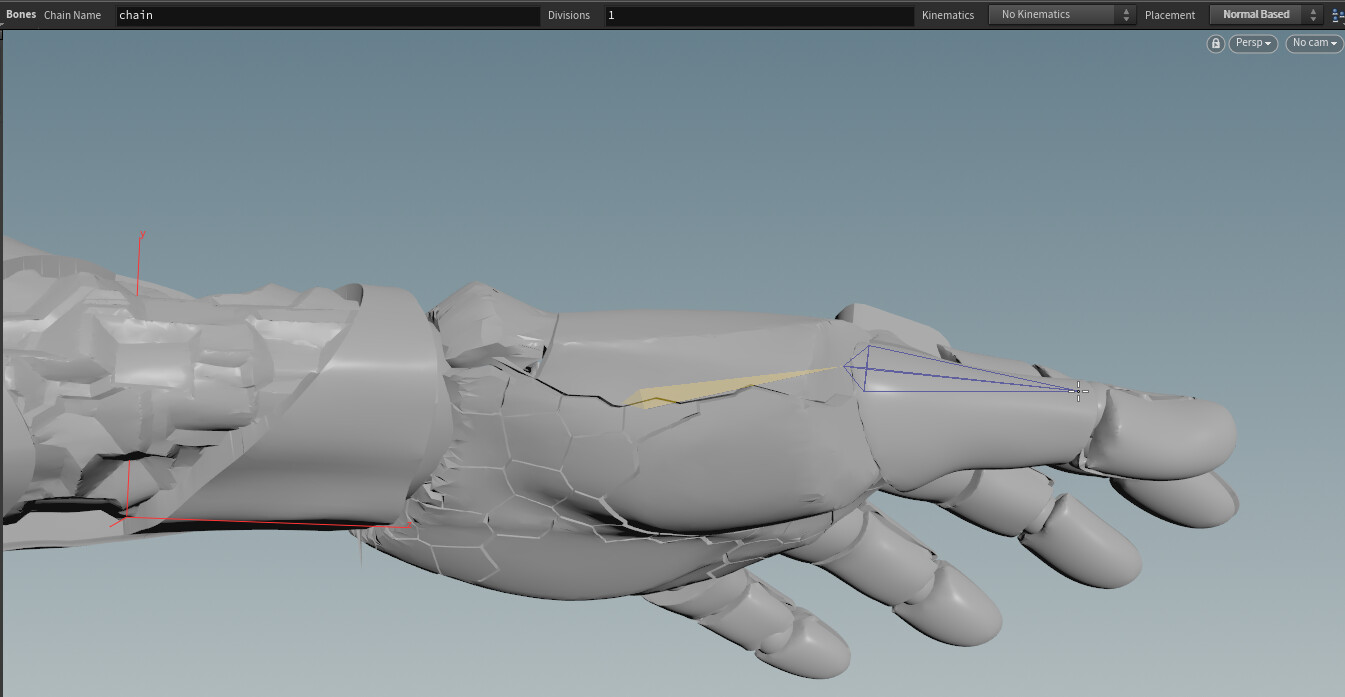
Where do you start the rig is with creating bones. In the viewport you can press TAB and type in bones (not bone). At the top of the viewport there are interesting settings for placing bones.

View based: Based on the view angle the bone will be placed. What it will do is that it will look from the surface you selected to the other side of the surface and find the middle. In the middle the bone will be placed and this is based on the view angle.

Normal based: Similar like the View based mode but it will look at the surface normal to find the other side of the surface.

Freehand: free to draw bones where you want.

You could also enable the construction plane and use it to place bones based on the construction.

When all the bones are placed make sure to check that the bones rotate in a positive value when rotating them in a natural position. For example if a hand model is in a fist pose all values of the rotations are positive. If it would rotate in a negative direction you can rotate the bone 180 degree in z-axis. (can be different axis depending on your rig)

Let’s say all bones are now in the correct place. What you will need to do now is clean the transforms this is a quiet useful setting. With this you will reset al the parameter values back to 0, this will still keep the original transform. You can still see this information by holding middle mouse click on the node. To fast clean transform bones, you can just select all your bones and that will work too.

Right now you might have a bunch of nodes and you will need to link them to each other. For example if you move the arm the hand and fingers are moving with it. This is done by parenting bones. Easy way to do this connecting the nodes to each other. What comes in handy is the “Keep Position While Parenting”, with this enabled you can easily make and break connections between nodes.

Another way of parenting nodes is to look in the shelf tools and under modify there is a parent tool. By using this it will parent nodes.

Here is a photo of my hand starting from the forearm to each finger.


Now you can create controllers for the bones. If you are familiar with rigging then you know that controllers will be create instead of adjusting the bones every time. In the tutorial they have included a shelf tool that automatically creates a controller setup. The tool will create 3 null nodes and the last one is then the controller with circle shape.

Eventually I ended up with 1 null node controller for each bone. I placed it above the bone so the bone is the child. I don’t know if this is the right but way but it work. you can see this also in the picture above where above each bone there is a green null node, this is the controller.

To assign the model to the bone you would normally use skinning but in this case have not done that. You can just parent geometry to the bones and that will work too at least for hard surface object with no soft skinning.

Since the arm is procedural generated I would like to automatically split the generated arm and assign it to the right bone or try to see if auto skinning can be an option.


Here is a simple animation with the rig. I will be going to ask the animator at the studio to help me a bit more out with this process. 


General Tips & tricks

This week I got more tips, I try to show tips and tricks that I use.

Save presets

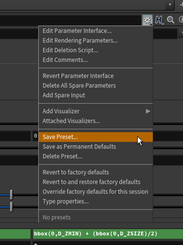
I might have mentioned it before but I found this super useful. All nodes have to option to save multiple presets or assign default values. You can use this for simple things or more complex settings.


Auto merge node

If you work often in the sop level the merge node is used a lot to combine multiple nodes together.  There is a easy way to automatically create a merge node

First select the nodes to merge. Then hold the alt key while drag one of the outputs of the nodes. Once released a merge node is created.


And as always thanks for taking a look at the blog. I felt this post might not be the most interesting one but animating the arm could be really awesome.

Feel free to share thought and see you next week!

Houdini Blog #11: Arm 2.0

General / 13 May 2019


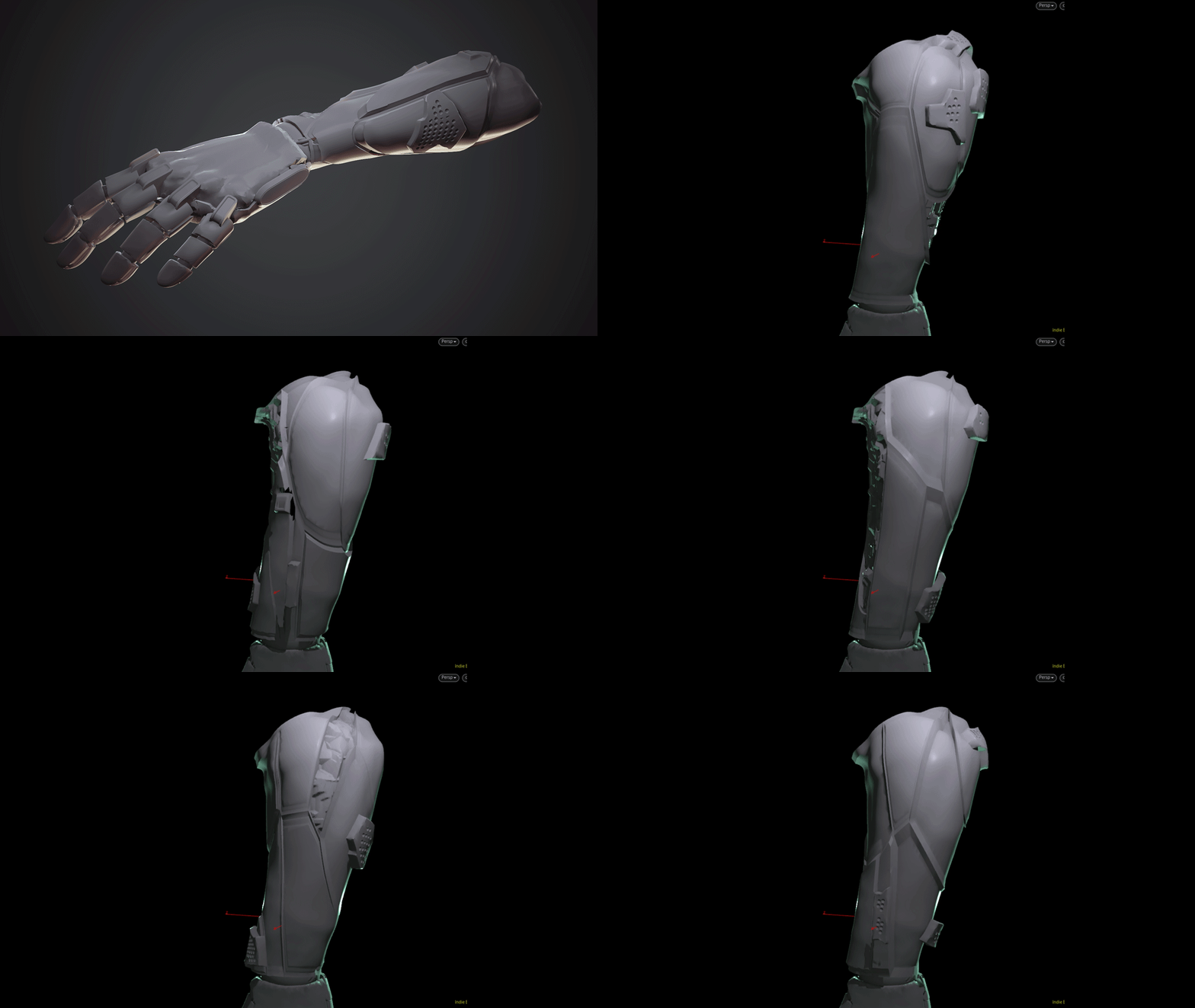
This week I continued working on the sci-fi arm that was created in post number 9. I want to see how far I can push it and will work on it for a few more posts. Feel free to share feedback, thoughts or questions about the project. 

For the arm I started back from scratch sometimes that can be the best thing to do. First steps was cutting the arm in 3 pieces. (forearm, hand , fingers) Then for each of these pieces there are different fractures and modelling to it.

After playing around with it for a few hours I came up with this result.

What to do after a Voronoi fracture?

Before continuing I recommend this video of Akira, it was mentioned already last post and the video is really interesting and a big help.

Check out Akira's talk https://vimeo.com/305053254 (subtitles in English)

Since previous post where about how the create patterns I will talk now about what you can do after you did a Voronoi fracture sop.

First is the attribute of the pieces. Each pattern created by the Voronoi fracture will created pieces. The number of these pieces is stored in the attributes. You can take a look at the geometry sprite sheet in here under the primitive attributes you can see something that is named name. You can also enable and disable different types of attributes and values. What can be useful is the Primitive piece. In the image below you can see the attribute created by the Voronoi fracture.

With these value you can use it do certain things. As small example I have put down a prim wrangle node and in there in the following, @piece = @piece%3. This is the modulo used here some of you probably know it. It will show the remainder after division of one number by another

In the image the colors of the sphere are representing the modulo results.

Of course you can make more complex systems and filter out the piece you want to modify.


Another thing that you can do is assemble it and enable pack geometry. This is used for simulations but you can also manipulate it to what you need. Enabling the create pack geometry will package up your model into an embedded packed primitive.

An embedded packed primitive stores a copy of the input geometry as part of the primitive’s data. Any copies of the embedded primitive will share the embedded geometry, potentially with significant memory savings.

A good example of what this can be used for this effect

To create something similar you can watch this video. https://www.youtube.com/watch?v=O_inXz-c-qM 


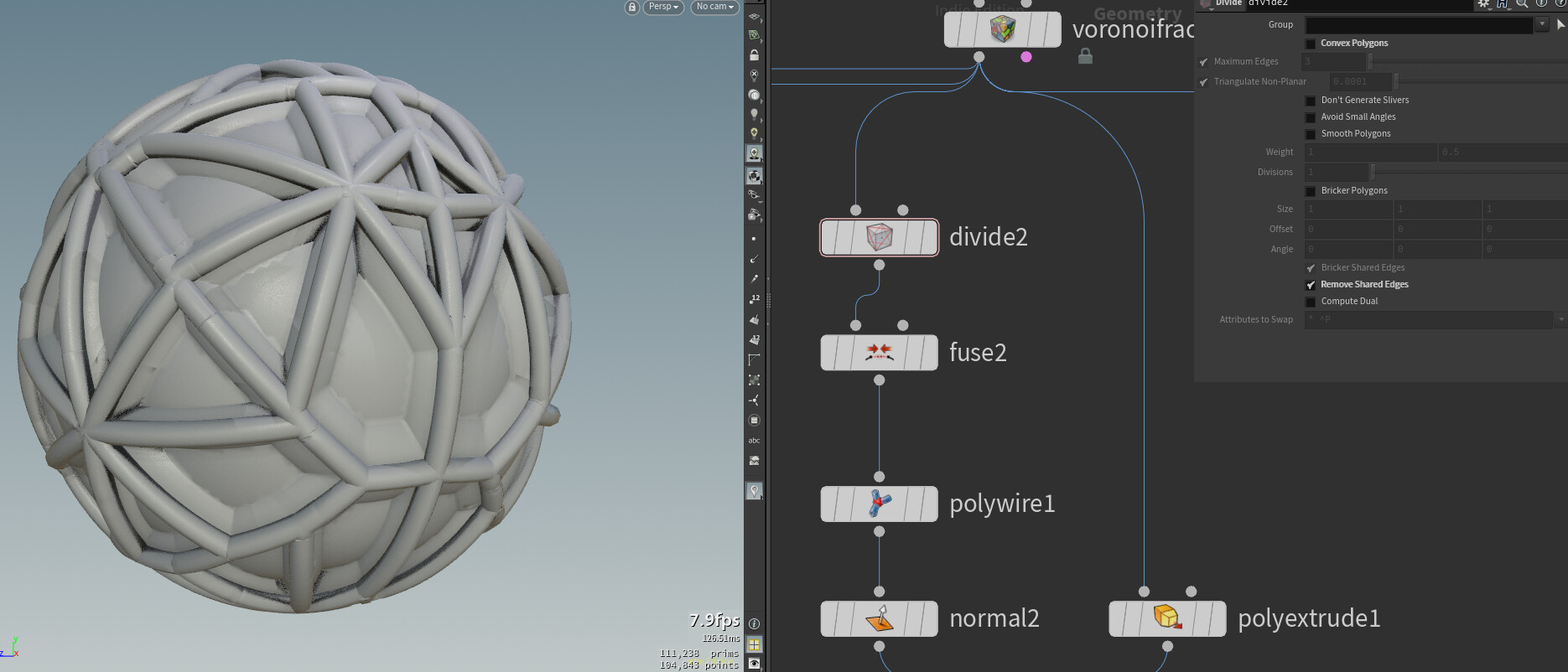
As last is extracting the lines of the cuts. This information can be really useful in some situations. The main node here is the divide sop. The divide is used for making the full model to quads or triangles for example. The feature to use here is the remove share edges, all the other settings can be turned off.

Sometimes I have but the divide in a for each loop to go over every piece but to be honest I forgot why. In the simple setup it worked quiet well.

Also doing a polywire to quickly create a shape around the line.


General Tips & Tricks

I have the idea the share now and then a few tips and trick of Houdini. It can be basic things but they are useful.

Creating shelf tools

You can simply drag and drop selected nodes in the shelf bar and save them. Each time you press that button you created the nodes will spawn. After a will when you made multiple of these it will save time and you won't have to start form scratch always. Keep also in mind that you can just make HDA's if need before saving everything in the shelf bar.

That's it for the post, I hope you enjoyed!

See you next week :)

Houdini Blog #10: Voronoi fracture

General / 06 May 2019


This week I continued on experimenting with noises and creating patterns. The focus of the post will be more on the Voronoi fracture sop as this can be quiet powerful. 

What is interesting is if you start layering multiple voronoi fractures. In the Gif below I have used 2 voronoi fractures and with that I'm able to create more variation in the shape. (This was inspired on the work of Akira)

Voronoi fracture sop

Last week I already mentioned that this node is used for fracturing your model to destroy it. But it can easily be used to create shapes and patterns.

In Houdini 17 the Voronoi fracture sop has changed and might miss features from the old one.

Before diving into more details I noticed that this node has been updated in Houdini 17. With this update they have added features but also removed some. What you can do is go to an older version of Houdini and copy past the old Voronoi fracture node.

New node 

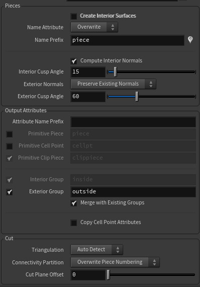
Some useful settings for the new node

-creating interior surface : As you want to create a pattern, there is no need of making geometry inside.

-visualize pieces: this is a small icon on the right side of name prefix, just click the icon to get a color visual of the fracture.

-output attributes: these can be used if you later want to access the number of a certain piece.


Old node

Some useful settings for the old node

-Cluster : with cluster you can have more control on where the fracturing is happening.


Creating the patterns/shapes

Now how can you create shapes? You need to get control of the points that are being used in the second input (which is called points for Voronoi cells). The most used way that I have seen is with the scatter node and then build in some control.

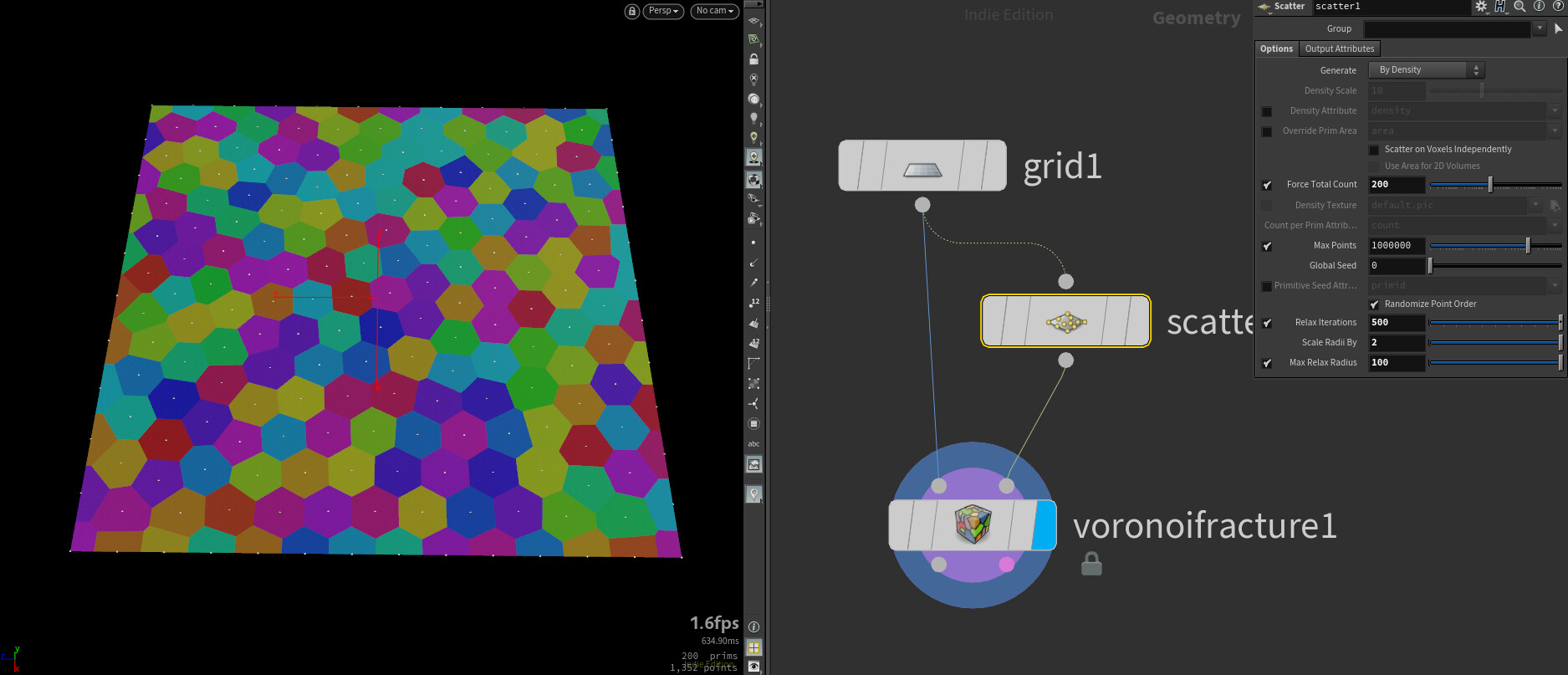
The scatter node is one nice way for creating some patterns. The node will create random points on your model.

In the scatter node itself there are settings to control how the scattering is happening.

With the relax you can make the distance between points more equal, this results in almost a hexagon shapes.

You can also use the density attribute to create scatter on areas you want. As example I took a measure node and when the attribute value is closet to 1 it will create more points. You can see there is more pieces at the blue areas that you can create with the measure sop.

You can also but down a mirror node if you want to get symmetry in the result.


It is also possible to cluster or group the scattered points together. With this you can create more panel shapes. Here is an example.

Note that for this method this simple way to get this is to use the old Voronoi Fracture sop.

After the scatter node place down a cluster node and in here you can set how many clusters you want to make. In the Voronoi Fracture sop enable cluster piece and you will see the result.

This is a nice way of creating panels but what if you would like more control in the clustering. If you look at the geometry spreadsheet you can see that cluster is just a point attribute. So what you can do is not using the cluster node and replace it with a wrangle where in the wrangle you create your own cluster attribute.

What I did is I created a point and created a pointcloud around that point. Every scattered point in that point cloud is now added to the cluster attribute. This way I have control on where points are getting clustered.

Small note here is that if cluster attribute equals to 0 it will not cluster the points, so it can be used in our advantage if you don’t want all points to be clustered.


As last you don’t have to use scatter to create you shapes. There are other ways to create it.

A simple example here is a grid with the fracture points also being a grid with more points. Then copying the grid and move it. I found this quiet interesting to see and the amount of shapes you can create.

What I just showed can look nice but the challenge here is that I used a simple grid to demo it. If you would try this on a more complex shape you can see that it is not that reliable anymore.


I hope with this you have a better idea on how you use it and create patterns and shapes. With the arm I created previous post this was mainly an arm mesh with scatter and use that in the voronoi fracture.

A few more good resource if you are looking for more.

- cgwiki : http://www.tokeru.com/cgwiki/?title=Houdini  (you might have to scroll down a lot)

-Akira :https://vimeo.com/305053254 


That was it for this week, this was already post number 10 :)

I hope you enjoyed the blog and found something interesting.

See you next week!

Houdini blog #9: Noise

General / 29 April 2019


This week I decided to look up more about noises and how it can be used to create shapes. What also happened this week was the Everything Procedural Conference. In the conference I was one of the speakers there talking about Houdini used as main creation tool for an indie game.

I have met amazing people during the event and I’m really happy that went to the Conference. After the event I explored more about noises and patterns in Houdini. In a GDC video, where they talk about the making of the rebirth video, they talked about how a procedural pattern is generated. So I found that awesome I wanted to do something similar.

And as always here is the result of this week.

Random VS noise

First of all I want to talk about Randomness vs noise. This was something I didn’t think much about. After watching this video the concept will be explained.

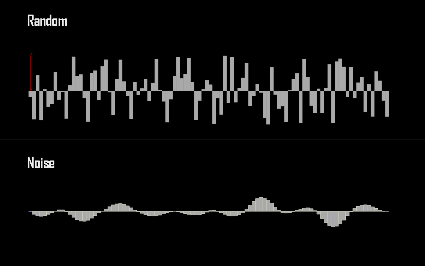
But in short, you want to control the values that you used to create something, you can see it is art directing the noise or the values. If you would use random values it is uncontrolled and can go from high numbers to low numbers instantly.

With noise there is more control and by default values will have a smoother transition between values.

Here is also a picture to show it more visually, this is can also been found in the video.

It is clear to see that with random values it is random and not consistent and will be harder to  control.

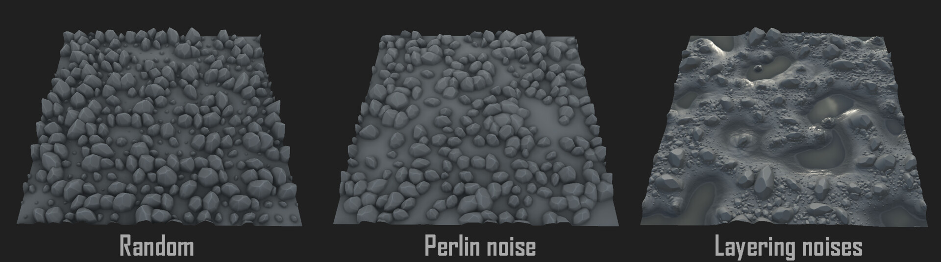
This idea can also be used in other software such as Substance Designer. In a tile sampler you can use a mask to control how the scattering will happen. Compare to a random scatter where it is random. Look at photo down here.

So if you will work procedural thing about controlling values with noise and watch out with using randomness. Not saying you should never use some randomness but if you want a lot of control. It might be difficult to do with random values.

VOP noises

After watching the video I started to explore more about the VOP and the noises in here. You can see VOP like VEX but with nodes. So if you feel more comfortable to work with nodes then code, check out VOP’s.

The main workflow of using noise to create patterns will look something like this.

I found it quiet useful to know.

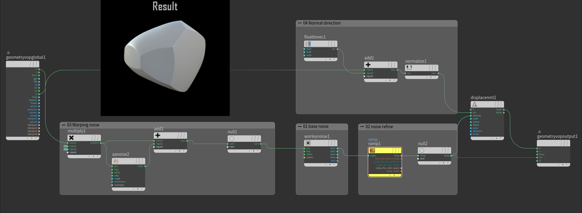
To demonstrate this more I build a simple rock shape generator flowing the workflow. What you will need is a highpoly sphere and a point VOP.

01 = Base shape and here is the worley noise used because this gives a good base.

02 = Getting more control, here you can just use a ramp and play around with it.

03 = Warping the points before the base shape. This is to create a more "unique" noise. So the worley noise will look less standard worley noise.

04 = This is the direction of the displacement.

Voronoi fracture sop

Then as last I will talk a bit about the arm that I made. With the VOP noises I didn't get that far for create something that I wanted. After some research I found that the Voronoi fracture sop is quiet good the create patterns.

The Voronoi fracture is mainly used for destruction but you can also use it to create patterns and shapes.

An example here is the arm. You can see at the top there is more control and a hexagon shape is visible.

A simple way the create this is to use the shelf tools. More specific the Shatter tool.

The trick here is to control the scatter node that will help decided where the piece are getting fractured. A tip here is the use the relax option in the scatter node so the points are less randomly placed. With this I make back a reference to the beginning where you can have randomness and noise. Best is to aim for the noise so there is control, you will need to decided how it is going to be fractured.

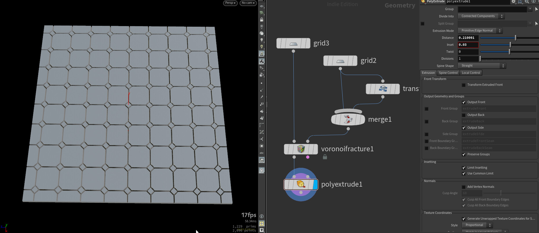
Further to create more interesting shapes I used the extrude to create panels on the arm but next week more on that.


Thanks for taking a look at the blog, next week I will show more about that arm and take it further.

See you next week :D

And feel free to share feedback and thoughts.

Houdini Blog #8: PDG part 2

General / 22 April 2019


This week I will continue on the PDG and take it a little bit further. I will show you some basics on how you could make a city generator with it.

Check out blog 7 for more about PDG.

You can watch this video about PDG as I it helped me for the blog.

Here is a result.

Creating Layout

Before we can generate houses we need a layout for the city. This part will be kept simple and in here there is room to make it bigger and complexer. 

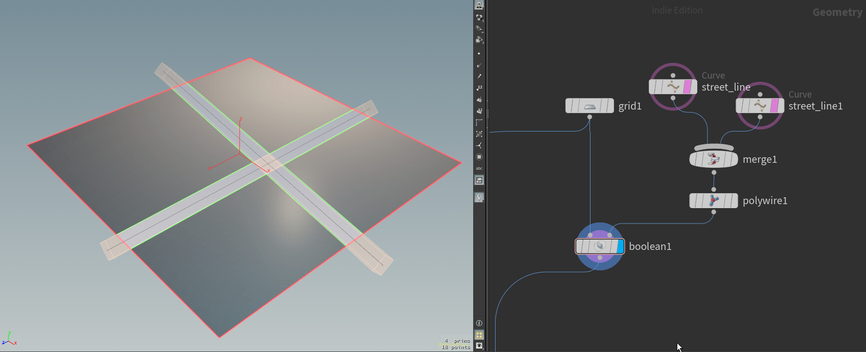
First creating a grid and some curve nodes. The curve nodes are representing the streets and Boolean them out of the grid.

The you can split the primitives by using a subdivision node in a for each loop. There is also an extrude node where I give each primitive and inset.

By using this expression you can get randomly subdivisions. Based on the number of loop iterations it will do a subdivision. Also by adding a sort node before the loop you can randomly change primitive numbers.

detail("../foreach_begin1_metadata1" , "iteration" , 0) % 2

Once you have a basic layout, you can now make a HDA or digital asset from it. Expose the seed of the sort node, so you can create random layouts.

PDG Nodes

In the TOP (PDG) you need a couple of nodes.
The order is like this:

-Wedge: here you create a random value that can be used later on, also you can ask here how many variations you want. The photo shows only one variation.

-HDAprocessor: With this you can load in your own HDA. Here you load in the layout HDA you just made. Also here I just the random wedge value and used it in the HDA Parameters tab.

-Geometry import: For this example the source geometry is set to Primitives. For primitive there will be a dot added on the node. On the picture these are 10 as my layout of the city is split into 10 primitives. (I took 10 because it was fast to calculate and my laptop can run it)

-Attribute create: Here are attributes being created and they are on each primitive different. So you can use this to make the height variation of the building. Example of a line you can use here

 (rand(@pdg_index) * 100) + 40 //will create random number for each pdg variation

-ROP geometry: With this node you can double click on it and open it. Here is the logic of the houses build.

-Wait for all: This is straight forward it will wait for everything to be calculate before moving forward.

-Geometry import: In here you want to use it as a merge node and enable merge input to do this.


Last thing that I wanna say here is to view the result you have to create a file node (sop) outside of the TOP. In the file node fill in the next line to see your result of the PDG.

`@pdg_output`

House generator

Then for the house generation part, I took some parts of my house generator that I build some time ago. You can find it here.

https://www.artstation.com/artwork/oOW8NB 

In the ROP geometry I build a simple version of a house generator and some parts of model placement doesn't make sense but it is about the idea and having a working prototype. Later there can be polishing done.

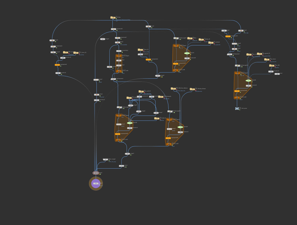
Here is the graph of the house part.

I also would like to mention that Houdini crashed a couple of times on my laptop because I wanted to generate a bigger city. As soon as I merged all the building together and want to view them, Houdini crashed. So if you don't have a good computer it might be getting difficult to make big cities.


That was it for this week. It was a busy with the fact that I will be speaking at Everything Procedural Conference but I'm happy I found the time to make this post.

Thank you for taking the time to take a look at the blog and see you next week. :)

Houdini blog #7: PDG Intro

General / 15 April 2019


New week, new blog :D. This week I followed tutorials of the new PDG system. I wish I had more time to explore the PDG but there is a presentation upcoming so I’m preparing that also. The event is called Everything procedural or EPC in short.

I will share some progress on the result that I have from the tutorials. You can find the tutorials on the Sidefx Vimeo channel.


What is PDG

For people who have not seen the Houdini 17.5 release video, they might have missed PDG. This was the big feature they introduced at the release. I can recommend you watching the video of Houdini 17.5 if you want to know more about Houdini.

PDG stands for procedural dependency graph. It can distributes takes with the help of the scheduler and computes them parallel. In other words we can generate multiple tasks at once (depends on your computers power).  Like a city generator is often an example. With the system you can generate large cities and generate multiple buildings at once. 

The big advantage here is that is we make changes to our city and only the parts that will have changed will be recalculated. Let say we have 500 buildings and 200 have been changed, then only the 200 buildings will be calculated.  As with other systems you might need to fully recalculate the full city.

With this I hope you will have a better idea of what it can do, it is of course possible to do way more with it. An other example is using the system to make tons of variations, this can go from a variation on a model to having variations in destruction to see what works best.

PDG: Wedging

Let’s start very simple. Wedging is used to create variation and is interesting to use. With wedging we can create random values for each variation.

First of all you will need to create a TOP network (here is the PDG system). Once in the TOP network create the wedge node.

With the wedge count you can ask how many variations you want. To show the results you need to cook the nodes. By right clicking you can select cook or press shift+g. Now dots will show up and this will be equal to the wedge count. You can click on these dots to see it in the viewport (as this is an simple example it should work, like in the gif).

Next what you should do is go to the wedge attributes and create one. For the example here let’s just use a float and set the range you want. Notice that by default random sample is off. With random samples off you will get with each variation the same value added linked to your range value. If your wedge count is 10 and range is set to 0 – 1. What will happen is that each count, 0.1 will be added. So if you want random numbers enable random samples. You can check the value by double clicking on one of the PDG dots.

Give your wedge attribute a proper name and you are ready to go. What you will have to do now is go in the other network where we have a procedural model or setup. I will share this small graph for random damage. In the mountain node you type @wedge_attribute and now you have linked the PDG with the procedural asset.

PDG: Baking

Taking the same system you just made we can add automatic bakes on each variation. Here you already get a taste of the PDG system where it will bake all the normal maps for you. So if you just made 100 variations it can bake for each of them a normal map.

The PDG system will bake all the maps for you automatically.

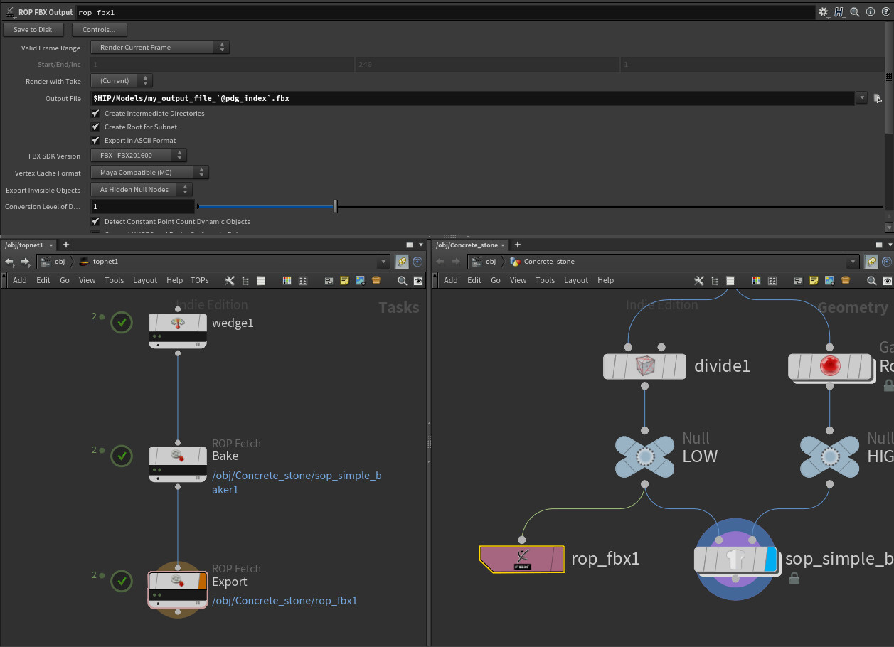
For this we need a ROP fetch and a ROP network. (Rop stands for rendering operation) In the ROP network we can create a simple baker this should be in the game dev tools if you have installed them. In the ROP fetch, fill in the ROP path to the texture baker and then cook to see what you have.

Look also at the naming of the file and use @pdg_index to get the number of the current task.

If everything went good you will see your normal maps in the folder. To be honest it didn't work always I need to research a bit more on this as often the cook would fail or empty normal maps would show up.


PDG: Exporting

As last let's say you want to export all the variations. 

Add a new ROP fetch and create a ROP FBX where your procedural system is. Then again fill in the path in ROP fetch to the ROP FBX. In the FBX node you can use the @pdg_index again to auto name them. 

I had no problems exporting models. I hope you can see that this can be handy if you need to create a lot of variations of something. Like you can make a car generator and everything is baked and exported for you.


This was a small part of what PDG is. I have more things to show but I feel this is already quiet a lot for one post.

I hope you enjoyed this post, personally I found PDG interesting and see potential in it.

If there are any mistakes or things that I have missed let me know.


See you next time!

Houdini Blog #6: Sweep with UVs

General / 09 April 2019


For this weeks post I continued working on the Apex legends Shield battery. Once I got to the unwrapping part, it started to get more interesting. I want to have enough control over the uv and place them in places where I want them to be.

An idea that I have for a while now is to combine the procedural power of Substance Designer and Houdini. Both of these programs have a plugin in UE4.

So in UE4 you can change the model of the capsule by using the Houdini engine in UE4. For changing the texture/material that will be done by the substance plugin. Both of these will have parameters to changes so I have the possibility to make the variation that I need.

Combining the procedural power of Substance Designer and Houdini in Unreal Engine 4.

Here is the result:


Procedural UV’s with the sweep

Making the UV’s procedural is not that easy especially since I want to have the uv’s in a very specific places so I can texture it in Designer.

With this post I would like to keep the focus on making UV’s with the sweep node. With the sweep node we can sweep a line along another line.

This can be used for making cable to more complex shapes. As example the base capsule of the Apex legend shield battery is made with a sweep, here is the result and with UV’s.

How was this made. There is a quiet common method for unwrapping this way.

First you convert both lines/curves to a NURBS curve with the convert node. Make sure to put UV order on 2 and enable interpolate through hulls. Then place a uvtexture node, in here set the type to arc length spline. With this in the uv viewport we are able to see all the points next to each other along a line. By default it will automatically fit all the point between 0 -1. This can cause stretching later on. What we do is we change the scale based on how long the input line is. With this expression in the X scale we can get control of it.

arclen("../OUT_line01" , 0,1,0)

OUT_line01 is here a null node that is between the line/curve node and the convert node. This is used here to get the information for to get the length of the line.

Last options to change here is the attribute class set  to points and with one of the 2 uvtexture node, you will have to add -90 degrees. The 90 degrees are for 1 line because the first line/input will be along the U axis and the second line/input is 90 degrees rotated and will then be copied along the V axis. Then we need to convert it back to polygons with the convert node and keep interpolate through hulls on. So it will look like this when you put everything together. Don't forget to put the sweep on One primitive at the time.

Problems with this method

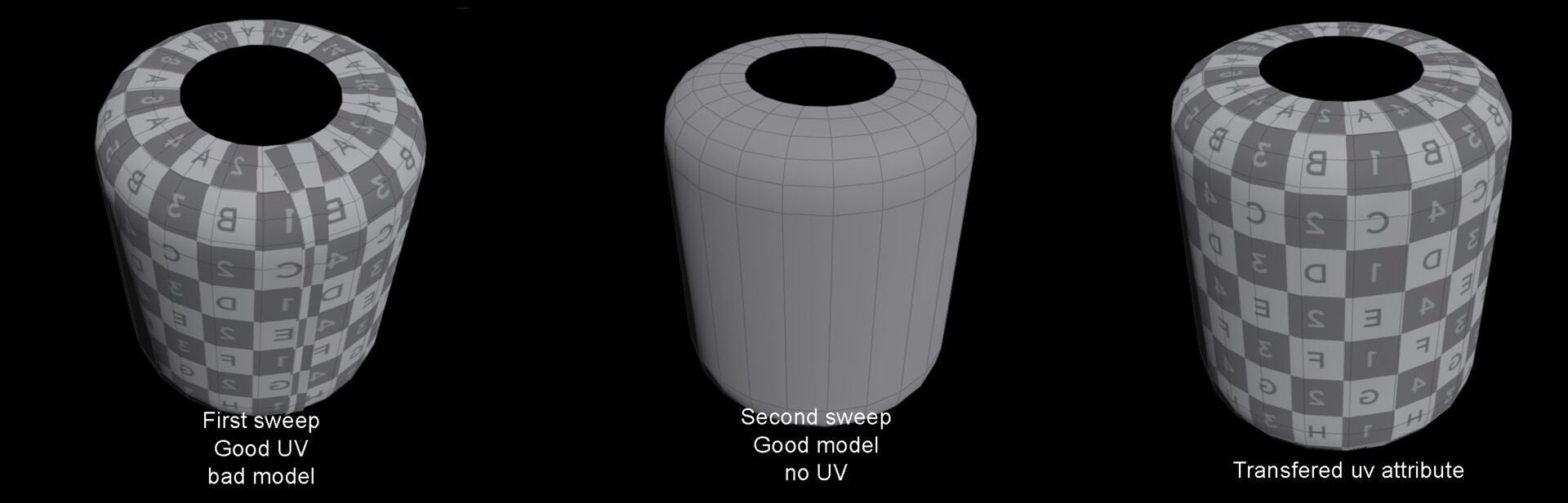
First problem that I saw is that when shapes are closed the part where the the first point and the last point come together the uv will be bad. Here is how it look like.

There is a fix for this. Thanks to this video for helping with that. Recommend watch it and checking out the channel.

In the video I also noticed that he was not using the convert nodes but was just using end nodes and set them on the unroll. This was interesting to know.By using ends nodes you will open a closed shape like a circle or custom closed line.

Now for fixing the issue, the idea is that we will transfer the attribute of the uv from one model to another model. So we have a version with the sweep with good uv’s put geometry that is ending in a bad way (First capsule on the picture). And we also have a version where the sweep has a good model output but not a correct UV. By using a attribute copy we can have the UV information of the version with good UV’s. But you will need to add a few things to make it work. Like setting the attribute copy to primitive group type.  The other thing is that you will need to add a fuse with unique points. The problem that we have with no unique fuse is that where the first point and the last point come together is that we have bad uv’s. So we have to split the points where the mesh is closing.

Small side note is I noticed that in Houdini 17.5, they have reworked the fuse node and I could not find the unique option anymore. What I did is that I still had a version of Houdini 17 on my laptop and copy past the fuse node.

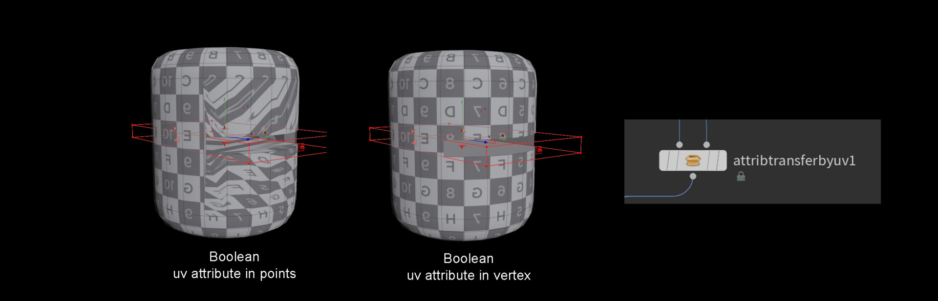
Second problem of this method is that the uv attribute is saved in the points. Which means later if you would Boolean the model it will break the UV.

It is an easy fix as there is a node that will convert your uv point attribute to a vertex attribute. If you would do a Boolean now it will keep the UV of the model.

Other procedural UV methods

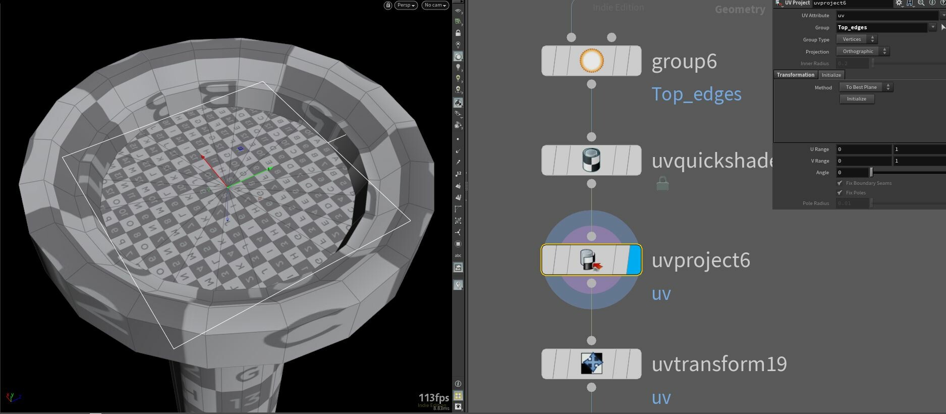
Trying to figure out on how to procedural unwrap the shield battery of Apex Legends, I used UV project also as another method of doing procedural unwrapping. Here is an example.

I was not happy with the result at the top of the capsule. So here was a UV project being used. With a group node you can make a group based on normal direction. So all the primitives facing up will be in the group and used in the UV project node.

Use initialize option in the UV project and it will automatically look for the best way of projecting. You can also use the radius parameter of the capsule in the scale. So if the radius is getting bigger the UV project will also get bigger.

As last what I do is using the uvtransform node to put the uv shell on the place that I want. In the end I have used multiple of them so I can controll of where the uv will be.

I can recommend exploring more the UV texture and the UV project node as they can be very useful.


That was it for this week. Hope you liked it and next week I will make my first steps in the PDG.

Houdini Blog #5: Apex Legends Shield Battery

General / 01 April 2019


This week I was inspired by an artwork on Artstation of Chris Burks.

Check it out here: https://www.artstation.com/artwork/aRaYBq  

So I decided to make the shield capsule as generator in Houdini. This post will be about the modelling part of how it is created. The generator wil be able to generate the 3 version/levels of the shield battery.

The modelling part will not be the biggest challenge of the project. What will be more challenging is creating good procedural UV’s and creating together with Substance Designer a final result. But that is the topic for next week as I’m still figuring out good ways on approaching it.

Apex shield Capsule

Here is the result of what I have made. This works also real-time in games engines like Unreal Engine 4.


The base Capsule

Beginning this project I start with making the base shape/capsule of it. Starting with basic bevel and extrude sop (I have not talked about this magic sop, dop, etc language but here is a link that should help)  you can get pretty far with it in this case.

When making procedural models you can’t select a face, edge or point. You want it to be procedural done. Always look at nodes itself to see if there is interesting features or options to save information.

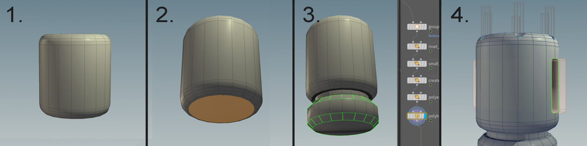
1.By placing a tube and putting the bevel sop, you can use the flatness angle option to bevel the correct part of tube. At this point we are already almost there :D

2.Next is adding a group sop that is selecting the polygon/prim that is facing down. There are of course other ways of doing this but I found using the group node easy.

Using that group information in a extrude makes it possible to always extrudes the primitive that is facing down.

3. In the extrude node you will find the Front group, enable this. We will use it to make more extrudes and insets to create our shape. Also look at the Front and Back Boundary group, use this later for beveling the edges we want.

4.Here comes a cool part, the Boolean. The Boolean of Houdini is pretty good. I was a 3DS max user and the Boolean there always create unnecessary points on the geometry. With Houdini the Boolean is clean and I trust it enough to use it in procedural systems.

Boolean is used for the space that the bolts need on top and the glass parts on the side.

The Boolean of Houdini is amazing!

To check if it procedural a quick test is that you go back to the tube node you started with and change the columns. 

Energy part

These are the parts that are moving in the animation.

This was made in a very similar way as the capsule. By starting with a tube then doing multiple extrudes (remember to use the groups that are created by the extrude nodes).

The handle is apart from this. It is created by using a curve and a sweep node. You sweep a shape you like around the curve.

If you want the 2 parts together I think you can get away with a Boolean.


Other: bolts and details

Some other parts are bolts and details both of these are using a duplicate node. What you do is that you duplicate them in a circle by changing the model positions or the pivot of the duplicate.

A good idea is to reference the amount of copies and divide the 360 by it. As result the copies will automatically evenly placed.

Good to know

Automatic beveling with a Boolean.

By using the correct groups we can do automatically a bevel on where the Boolean was. Enable the A-B seams as group and plug that in the polybevel. As result we have a bevel on those edges. Check also the other groups you can save, you never know when it can be useful.


For loop with an extrude 

Something that is interesting but not have been talked about is for loops. In this simple example I show to use of it with an extrude node. In total in the example there are 10 loops. Each loop a extrude will be added. What is also happening here is that every loop we are overwriting the extrudeFront group, which gives the result that I want.

To make it more controllable we can add some math. Here again simple we multiply the inset with -0.01 and the current number of loop.

You can acces the current loop number by creating a metadata node, you find this in the repeat_begin1 node (here in the pic). Write the following line to get it.

detail("../repeat_begin1_metadata1/", "iteration",0)

You can get interesting results by adding extra elements in the formula. Like what would happen if you add a sin?


And as always thank you for taking a look at the blog. 

If you have any feedback or topics that could be interesting for the blog let me know!


Houdini blog #4: Quick bend and FFD node

General / 25 March 2019


This week the quick bend tool got some polish and is working quiet good. One thing that I noticed is that I found it difficult to found information about the buttons in the HDA. So at the end of the post you can found more about buttons in Houdini. Later this week I created a FFD node for Houdini.

Quick bend

Polished the quick bend node and here is the result. Materials are from Substance Source.

 Gif is an example of a model that was made in minutes with the quick bend. 

Some of you have asked on Twitter to know more about it and here is a breakdown of the mean idea. By using the bounding boxes (bbox) in the standard bend sop of Houdini, you can already do a lot.

In the image below you can see that the bounding boxes are used to automatically get the origin for an object to bend. These setting here are specific for bending around the X-axis. To make sure that the Capture Origin is in the middle I add Y and Z size. By adding this the origin of bending will be in the middle (look at the handler in the viewport).

Bounding boxes are very useful and can automatically do things for you.

You can make a HDA from this like me and start adding more feature on top of it. What you also can do is save preset on the bend node itself. Save preset are handy to use. Every time you need to bend an object you go in the presets and select the one you need.

Another example of presets that I use is in the transform node to automatically place a model on the grid so the pivots are correct.


FFD/Lattice deformer

Next is a FFD node, some of you that gave used 3Ds max know this feature (I was once a 3DS max user, but switched to Houdini :) ). It is a box around your model, by moving the vertices of this box your model will be deformed. Here is the result of it and see for yourself what it does.

Press the edit button and a box shows up that allows you to deform the model.

It took me some time to figure it out. After a few hours of trying, I was not really happy with the result. Then decided to make research and found a really good video on this. Here is the link ( https://vimeo.com/210121561 ) It will be shown in a vop network. After following the video I made it in a wrangle. I was very close with my own system, the one thing that I didn’t think of was the pcfilter (can be used with point clouds). Pcfilter can calculate the average information of a point cloud. So you can ask to the pcfilter the average normal information. (This was also mention in the Joy of VEX that I followed, Day 20).

Other software is using the name lattice for deforms like this. When trying out the Lattice of Houdini, I felt I could improve on it. By making the box around the model automatically.

What I wanted for the tool is that you only need to plugin the model and it automatically creates bounds.

In the picture you see first the setup with Lattice. And under it the custom FFD and how it looks inside the HDA.

Inside these wrangle there are 2 lines of code in each of them. The first wrangle calculates the difference between original bounds and the edited bounds. So if you didn’t change the points position it will be 0. But when you move a point it will get a value. We save this information in the normal, with this you can also easy see the result if you enable normal in viewport.

@N = -(@P – pos2) ;

The next wrangle will move the points based on the normal information that we just added. But first creating the point cloud. The point cloud used the second input (bounds look at the picture) for creating the point clouds around it. With this we select all the points that will be influence on your custom model. Then use the pcfilter to get the average normal information of the added normal and directly added to the position of the model.

The line looks like this

@P += pcfilter(pcloud, 'N'); //getting average normal and using it in the point pos

So points that have been moved, will have a normal value that is not 0. With result that the points will be moved.

Next challenge here is to make the edit sop editable will it is the HDA. That is why I made the next topic, Buttons in HDA. Because here is where the magic happens.

Button in HDA

Overall I could not found quickly information about buttons in Houdini and how to use it in a HDA. By default if you create a button not that much is happening.

After some searching I found that the useful part of the buttons are the Callback Script text box. In here you can type a piece of code that will be used when pressing the button. 

The coding languages here are Hscript and Python. For some reason I found it easier to write it in Python, I don’t know why. But as long as it works :D

To set for example a float value you use this in the callback script

kwargs['node'].parm('bend').set((180));

But you can also start calling a module that you make in Python. This is exactly what I did for the FFD, to make the edit node editable.

Calling python function :

hou.pwd().hdaModule().editIt(kwargs)

So editIt is a custom module created for this HDA. You can write the module in the HDA properties, go to the script tab and add a Python Module.

Here is part of it that was the most interesting.

edit = sopnode.node("Name node to edit")
edit.setCurrent(True, True)
viewer.enterCurrentNodeState()

As you can see we sort of force Houdini on the node that we want. We set it to current node to look at and we enter the node state in viewer. This gives us the result that we can edit the edit node in a HDA, when pressing the button. 

https://www.sidefx.com/forum/topic/18863/  more info on how to make.

Thank you so much for taking a look at the blog, I promised my self to keep it more compact the blog put ended up show more.
Hopefully see you next time.


If you have any thoughts or feedback feel free to share it.