Website powered by

Houdini Blog #23: Decals

General / 20 August 2019


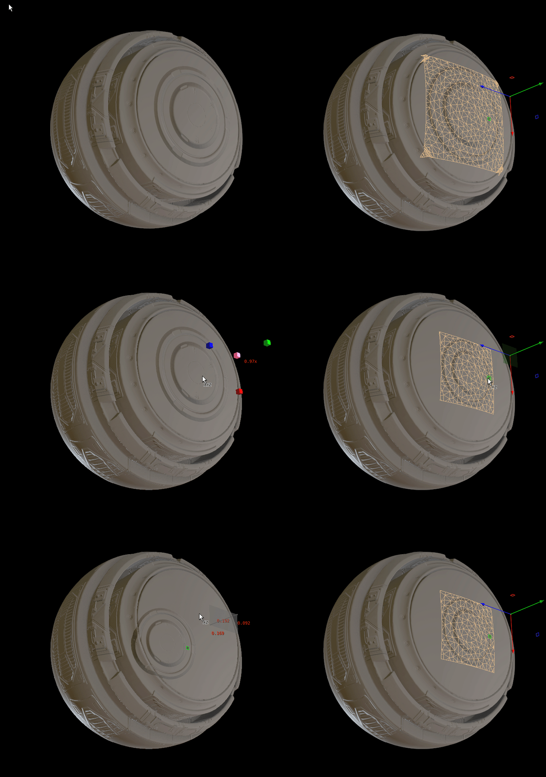
This week a game tool got my attention, the decal projection. With this node you  can project a heightmap on  a model. The result will be a shape following the model with a normal map that holds the detail of the heightmap.

Some of you have seen the decal machine for blender, this decal projector has some similar ideas.

Here what a you could do with it.

How to use it

There is no dedicated video on this yet for how to use. But it was in a demo of GDC 2018 https://vimeo.com/263406952  (at 14:30)

To use it, you plug in the model you want the decals on in the decal projector. Next is to link to the heightmap by filling in the location of heightmap.

In the viewport you should also see a handler, with this handler you can manually place the location of the decal.

From what I understood in the video it has support for the Houdini baker. Which means that if you wanna bake a low poly and your high poly has decals, the decals will also be in the normal map for the low poly. (Didn't test this yet)

Custom tweaks

After using this node I made a few tweaks and changes. This is an advantage you have with the game dev tools is that you can open and change them.

A change I made is that you can now select a mode of how you wanna place the points. 

    As first option is the default with using the handler.

    Second is a scatter option, this will scatter points on the model and on each point there will be a decal added.

    Third option is using the second input of the node where you put points in the input and will create decals based on the points.

With the second and third option you will need to calculate the correct align of the plane to project. You have a point and on that point a grid will be copied but it needs a good rotation so the decal is placed in a good way.

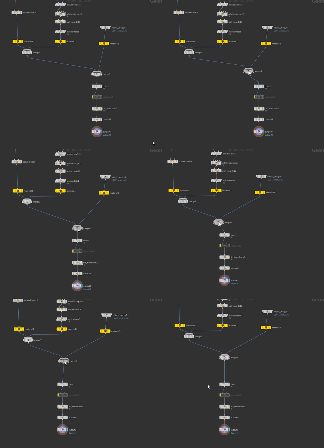
As example here is a breakdown of the second input. What you first want to do is create a normal node and add normal attribute to the points. When creating now a scatter node the normals have also been transfer into the points from the scatter. Doing a copy to points now will result in good rotation of the model that is copied. 

To get more control over how models are copied and their rotation, you can use the up attribute. Houdini will recognize up by default, here is a list of more attribute you can use to get control over copied models. http://www.sidefx.com/docs/houdini/copy/instanceattrs 

You can use the following in point wrangle to change the up vector.

@up = {0,1,0};

Further you could expose more settings or build on it.  I have added some settings for the normal like flip and strength. Also for materials I exposed parameters so I can give in my own diffuse, rough and metal.


That was it for this week. 

Thanks for taking a look at the blog, hope you found it interesting.

Houdini Blog #22: Tips and Tricks

General / 06 August 2019

At the blog this week there are a few tips and tricks. After finishing the Artstation challenge I thought it could be a good idea to share tips and tricks.

These tips and tricks are focused around the node network, from getting a clean graph to working faster in the network.


1. Colors and shapes of nodes

Starting with a basic tip that helps you out organizing and making your graph a bit more readable. Giving nodes a different color or shapes will help you out in bigger graphs or can be used to mark nodes that need a rework or optimization. You can create rules for what colors and shapes mean like red means that it is not procedural but needs to be procedural in the future. Make sure if you are working with other people that you have the same rules so there is no misunderstandings.

Shortcuts for colors are "C" and for the shape "Z"


2. Moving nodes around

You can move nodes around by selecting them drag them around. But in Houdini you can also hold control or shift to move whole node networks based on the current selected one.

With Control you will move all the nodes underneath the selected node and with Shift you move all the nodes above the selected node.


3. Align nodes

After you have build a network of multiple nodes you might need to organize the layout  of your graph. There is a fast way of automatically sorting the network if you press "L" but I'm not always a fan of it as it will change the whole layout. 

By holding "A" you see that the mouse cursor changes icon, now if you click and move your mouse in a direction it will align in that direction. If you move the mouse downwards nodes will align vertical. Notice that based on where you click with the mouse that is where it starts to align.

4. Reference a full node

In some situations you might need a copy of a node will keeping the same values linked to each other. By Alt you can copy a node and with Alt+Control+Shift you copy the node and it is fully referenced to the original node. I not using it often but it is good to know that this is possible if you want to reference the same node multiple times.

Hold down Alt+Control+Shift to create a referenced copy.


5. Extract content of assets

In Houdini you will find a lot of Digital assets or you have your own Digital assets which I definitely recommend doing. It can happen often that you want to look into these networks. You can unlock the HDA and go in the network but you can also "unpack" the HDA. If you click on extract contents it while swap the HDA with the network of the HDA. This can be interesting if you found a HDA that does something close you want, by extracting the nodes you can then adjust the extracted node network and make your changes to it. You don't have to worry about overwriting the HDA as you extracted the nodes.

6. Quickmarks

Quickmarks allows you to switch between your networks fast by pressing the 1 to 5 keys. That means that you can store 5 locations you want to jump to. So if you have a network with multiple nodes in the object level or multiple sub-networks, this will make your life easier switching between networks. Like you can set a Quickmark for your geo to destroy (SOP) and you set a quick mark for your simulation network (DOP). This feature was added in Houdini 16 and maybe some of you might have missed it.

Hold Control + Press on of the numbers at the top of the keyboard. Example Control+1 , every time the number 1 key is pressed you will jump to that view.


That was it for this week hope you enjoyed some of these tips and tricks!

See you next week, and feel free to share feedback or thoughts about the blog.

Houdini Blog #21: Particles for UE4

General / 30 July 2019

This week I made some particles for my scene. With Houdini in unreal engine 4 I could control how the particle flows in the scene.

For this tool I watched the tutorial of Andreas Glad. Definitely check out his channel if you are interested in particles.


This is the result of the particles for the scene. Took me about a day of work.

Lines tool

This tool creates lines for the particles. With the Houdini Engine you can control the lines in UE4 or other game engine. In the video below you can see it in action. (video is realtime)

The result will be a mesh that is bakes from the Houdini Engine. 


To get a detailed breakdown I recommend watching the video at the beginning. Here I briefly go over it.

The image below shows the very base of the tool. You can see that it is a sweep with the line/curve as input.

In blog #6 I talked about use the sweep and uv's so I won't explain it here.


What is interesting in the sweep sop is the transform controls, you can see these at the bottom of the sweep.

In the image you can see that they are linked to the parameters of the HDA. Notice that in the Scale, chramp was used. With chramp you can control the scale value with a ramp. For the chramp to work you will need the position and the component index. Position will be PCT (PCT is here percentage along the curve ) and the index is 0.

With these value you can make nice twist and curves in the line.

To control the curve in game engine you will need to make it editable in the HDA.  Go to edit asset properties and add the curve to the editable nodes. 


A quick trick for creating multiple lines is to use the duplicate. By using the duplicate on the line before the sweep, you might get a better result that works form different angles. In the video below you can see how easy it is to reference values to each other.

By drag and drop you have the option to reference channels.

Vectorfields

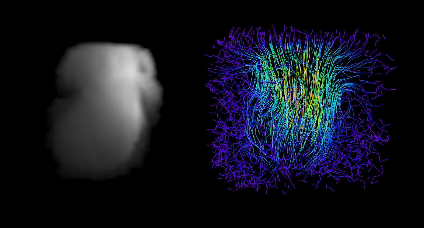
With Houdini you can also create vectorfield. With these vectorfields, you can use them in a particle system to control how particles fly around. So based on the vector direction a particle will decided to go that way.

In the image is a smoke simulation create with the shelf tools and with the game dev vector field sop you can get a vector field. This is also based on frame, so each frame as the smoke goes up the vector field changes to match the simulation.


I didn't have the time to get good examples but I found some great work on Artstation of Dimka Sokolov.

This is what you can create with vector fields in UE4, vector fields made in Houdini. Check out it here for more shots.


This was only a few examples of creating particles with Houdini, there are more ways of making particles such as spritesheets, vertex animations (VAT) or Niagara.


That was it for this week! Thanks for taking a look at the blog and see you on the next one.

Feel free to share your thoughts and feedback.

Houdini Blog #20: Snow + L-system

General / 16 July 2019

In this post I will talk about how you could build a tool for placing snow on top of models and place a few twigs on it. This tool will be used for my Artstation Challenge. 

With this tool snow is placed procedural on models you select in the game engine itself.

Here is an example of that.

Snow buildup

With this tool there will be automatically snow buildup on models. Doing this by hand would take some time and with a procedural tool you can get quicker variations on it. This tool works in UE4, so based on how your model is positioned in the scene it will create snow on top of it.

If you have installed the game dev tools you can see that they made a tool already for this. Trying out this tool, it have a result that I was not really looking for. I took some ideas of how they approached the tool and made a custom version out of it.

In the picture below you can see a comparison of the game dev and the custom version. You can see that the game dev snow does a good job but you feel that the snow felt perfect right on top of it. In the custom version there is an option to choose a direction the snow comes from.

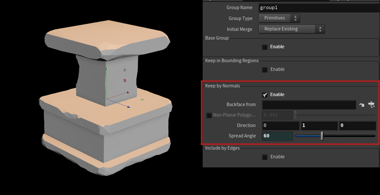
The main "trick" you can use here is a group node that looks at the normal direction of the model. Like in the image below where you can see that the prims facing up are selected and with the spread angle you can control it more. With this you can create a base pass for the snow.

To place the snow you can approach it similar like the game dev snow tool.  With the group that has been made you can use this group in a scatter sop. This results in points that are placed on the top surface of the model. Next you can copy to points sphere models on the points. After that you can use a voxel to combine meshes and smooth it out.

With this you have a simple system to get quickly snow on top of a model.

To get more direction control you can again use a group sop for this. One way to do it is after you created points with the scatter sop, is to delete these points based on the normal direction they are facing. 

Make sure to give your points a normal otherwise the group node has no information to look at. The image below shows the system, it is not complex and does an okay job. Exposing the values in the group sop you can control where points should be delete.

L-System

You might have noticed that in one of the pictures in the beginning there are twigs sticking out of the snow. These where made with a L-system.

A L-system is a parallel rewriting system and a type of formal grammar. This is often used to create plants, trees or organic shapes/patterns.

Resources to know more about it

Books: The algorithmic beauty of plants http://algorithmicbotany.org/papers/abop/abop.pdf 

Video:  https://www.youtube.com/watch?v=RtWxMraDfdA     artstation link of creator of the video

Procedural tree with L-system https://www.artstation.com/sercan/blog/qV2/houdini-procedural-tree 

On Wikipedia there are some examples you can try for yourself. Example 7 on Wikipedia shows a fractal plant, filling in the rules in Houdini will create the same result as on Wikipedia. Rules from Wikipedia (X → F+[[X]-X]-F[-FX]+X), (F → FF) and in the picture you can see them in Houdini.

Here is something I'm experimenting with.


Houdini Blog #19: mesh detail part #2

General / 09 July 2019

This week I continued working on the Artstation challenge. I have refined the blockout, made materials and shaders. In Houdini I tried out more the mesh detail sop. I have encountered some issues and I will show them, with a solution that can work. Also the outputs of the mesh detail sop are high in poly count and I made a small tool too keep detail around the edge and reduce the other parts more.

Here is a shot of the scene so far. Here is link to the progress: https://www.artstation.com/contests/the-legend-of-king-arthur/challenges/69/submissions/48664 

Tips on the mesh detail

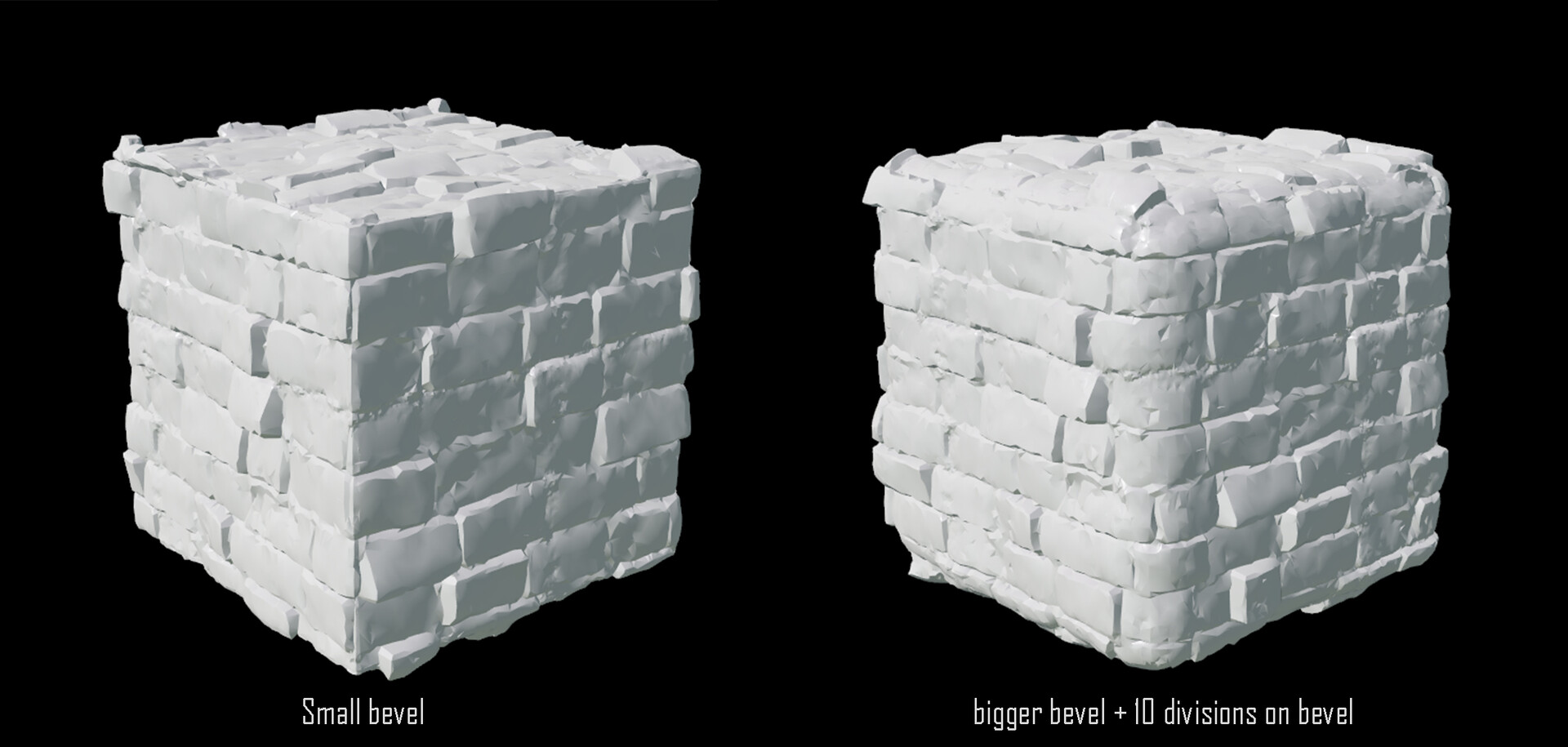
The first tip that I want to talk about is that edges should have enough bevel on them and also a decent amount of polycount. In the picture below you can clearly see the difference of changing the bevel. In general I prefer to increase the bevel so the result is smoother, also the small bevel bevel can feel low poly especially if you polyreduce.

Another part of having a good result is UV's. They should not overlap, this will create conflicts in the tool. Further is where the seams will be. This can be a bit more difficult, you can't just auto unwrap and hope to get a good result. Best way is to manually make the seams around the model. This way you get control of where seams will be. Like putting a seam in a 90 degree corner might not give the best results, that is where the bevel can help out.

In general you should think about where seams will be, the less the better. The picture shows an example of what can go wrong with 90 degree corners.

Optimize the result

After doing the detail mesh, you might have a model that is quiet highpoly. For me that could be around 30K polygons, which will be a problem if there are a few of these models in the scene.

To demo this I will take the pillar as example. With a polyreduce it already does a good job of reducing it, but by default it does more a general reducing. What you want is that the details of the edge/silhouette are still there.

The image above show the general idea on how you can reduce the model based on the edges. To get the information of the edges you can use the measure sop or the curvature sop. In this case the curvature sop was used.

To transfer the information you can use the attribute transfer sop. Select the type of attribute and it will be transferred. If you look under "conditions" you have some control on how the attribute is transferred. 

Once you have the information on the edge, then you can reduce based on this attribute. In the polyreduce sop there is an option to reduce based on attribute. If this would give the result you wanted, you can always transfer the attribute in a group and use the group in the polyreduce.


That was it for this week.

I hope you enjoyed reading it and see you next week.


Houdini Blog #18: Detail mesh

General / 02 July 2019

This week originally I was going to continue to write about the clouds but I decide to put it on hold, I also need to do more research on it. Instead of the clouds I will be joining the Artstation challenge. For the challenge I will make a environment in UE4 with Houdini as main software. Later in this challenge I might be needing some clouds so I can look back into the clouds more.

So I hope that this will be interesting for you to see an environment from start to finish build with Houdini. During the challenge I also going to try new ideas and workflows for creating the scene. In my blog post I will share details on how certain things where made in Houdini and on the challenge page will be the scene.

With that said the first idea that I want to explore more is the mesh detail node. (this node is included in the game dev tools)

The mesh detail node will create details on your mesh based on a second input model. By converting a height map in geometry I can then use it to detail my meshes.

Here is an example. Starting with a blockout model for the pillar and the mesh detail will create the bricks based on the substance Designer texture. (material is from Substance Source for testing)


How to use the mesh detail sop

To use the mesh detail sop you first of all need a model that you want to use it on, like a pillar, wall ... . What the model will also need is an unwrap because that is how the tool works more on that below this part.

The second mesh/input you will need is the details you would like the have on your model. This second mesh will be a plane/grid. You can model or sculpt this to get the look you are looking for. What you can also do is use a height map for a Substance Designer material.

To convert your height map into geometry you can use a point VOP. With a grid as input, in the vop you can decide if the points on the grid should go up based on a height map. The grid that is the input has an unwrap, this uv attribute is stored on the vertex. Knowing this you can access the uv attribute in the point vop by using an import vertex attribute. In here you fill in ‘uv’ as this is the information that you need. Then you can use a color map vop to load in your own texture. Notice that you need the u an v floats apart, so us a vector to float to get this information. Once you loaded in the height map, you will need to use the luminance vop to get only a grayscale out of the result. This information is the used in the displace along normal vop, with the luminance data as the amount for the displacement. Once you build this system, you could save it and make a HDA from it.

Now everything should be ready to use the detail mesh sop. Plug in your “block out” model (don’t forget unwrap) and the grid with the texture displaced in it, by default you should already have a result. What you can also do is reducing the grid in polycount if this would be already high in count. (later I will need to build a tool to reduce polycount but keep the nice detail on the edges)

The node itself doesn’t have that many settings, starting with some basic settings such as scale, rotation and depth (intensity). Other settings are the mask by color and the seams strength. With mask by color you can specify an area of where you would like to see the detail, you can add color by using the color sop or a paint sop to paint the area of detail. The seam strength can be used to get better transitions where the uv seams are, because the tool works based on your uv that means that seams can be visible.

Notice also that the uv of the model is changing with what settings you are using, so you don’t have to worry when you apply your tiling texture that it won’t match.

Photo shows first tests in game engine.

How it works

For those of you how are interested in how it works, here is a small explanation. (You can also open this node in your project, like most of the game dev tools are) Like I mentioned above here it is based on uv’s, so a good unwrap will be key to get good results. The first step the tool will do is unfold the model based on the uv and transfer from world space to uv space. The model is now a 3D version of your unwrap that is placed between 0-1 values. A few weeks ago I did here also a post about this way of working.  With this layout the tool Booleans the grid with the texture in the layout version of your model. With result of having now details in the model but it is still in the uv space. After converting it back in the original form some detail got lost along the way. With this method it is only able of transferring 2 axis data. After this in the tool they try to reconstruct back the third axis, this is done by saving information in the attributes.

Photo should give you general idea of how it works.

I have tried more complex shapes and then you can see that the tool will have problems reconstructing the full shape because of the third axis, this is difficult to get perfectly back. But in the case that I’m using it for the challenge it works fine. In general I think it does a good job if you use your tilling materials.


Paul Ambrosiussen did a tutorial on how to use the tool https://vimeo.com/288159065 


That was it for this week, I hope you enjoyed it.

Feel free to share feedback or question you have.


Houdini Blog #17: Clouds

General / 24 June 2019

This week I did some experiments on how you can make clouds for games. I have tried out a couple of different approaches, these are Raymarching shader, imposters and spritesheets.

These 3 have each there pros and cons. For making the clouds itself is where Houdini comes in. Houdini has a quick way of making clouds with one node.

This is the result I have with raymarching shader.

I'm still not 100% happy with the result and I will continue a bit more to see on how it cloud be better. Ideally I would make something that has enough control, has better quality and has the possibility to work with lights in UE4.

Houdini clouds

First what you will need is clouds, these can be created with Houdini. You can take a simple shape like a sphere and make it more interesting, the mountain node will be useful here. You also don’t need to worry about the topology of your model as you will convert it in a cloud anyway.

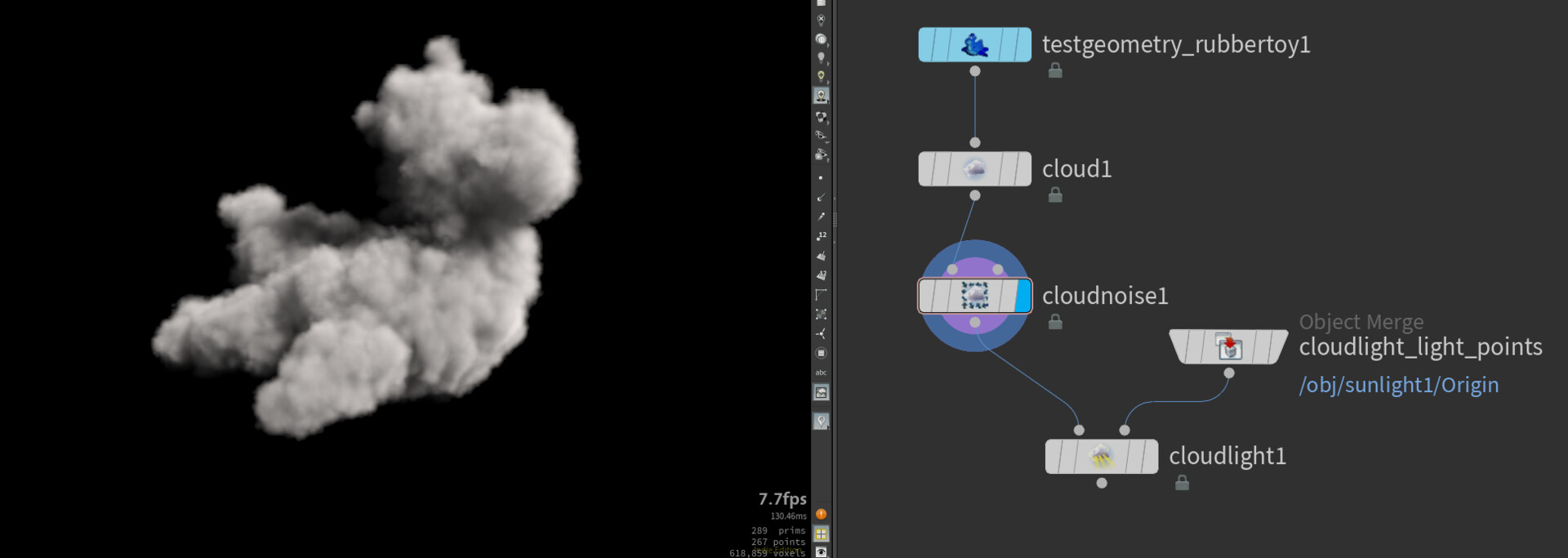
Then use the clouds node to convert the geo to a cloud shape. If you are interested in how it works, you can open the clouds sop and see all the VDB sops that where needed. After that you can add some extra noise with the cloud noise sop and that is the basic setup for making clouds.

What you can create in Houdini Is a sky. This is a sop and it will need an input. This input is the bounding box of the sky.

You can combine these 2 types of creating clouds. You can create a sky and if you are looking a very specific clouds you can use the cloud nodes for that. I kept this part basic, so I could put more time in how you can bring this in a game engine. Right now you have a volume in Houdini which you can’t simply export to fbx and import in UE4.


Raymarch shaders

The first way I wanted to try is with Raymarching. Before you continue I can recommend you watching the UE4 video on these volumes in games engine (They also show how to install). Ryan Brucks has build awesome tools and plugins so I can recommend also checking out his work.

This is cool and good looking way of getting the clouds in game. One big downside is that my laptop has trouble with performance. With a Ray marching shader in the scene I have about 10fps. So keep in mind that this will require a decent computer.

Here is one of the early tests.

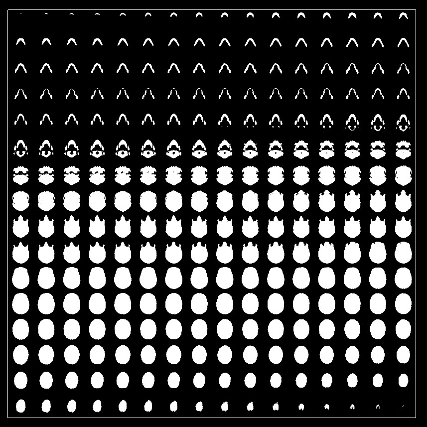
For the Ray march shader to work you will need to have a texture that is representing your volume. This texture will include multiple slices of your cloud. With that texture it is able to reconstruct the cloud.

In the Houdini GameDev tool they have included a node that creates this texture automatically for you. It is called Volume texture sop. In here are a few settings and most is straightforward to use. If you change the resolution it will automatically change the other settings.

After pressing render you should have a texture similar like this.

Import this in UE4 and use the raymarching shader (M_VolumeRayMarch_Lit_LinearSteps). Plugin the texture and set the amount of frame equal to the amount you exported from Houdini.


Imposters and spritesheets

After trying out the Raymarch shader from Ryan Brucks I didn't expected that it would be so heavy for my laptop. So I looked up other ways.


What you also be possible is making a imposter of the clouds. For you not familiar with imposters, an Imposter is a very low poly model sometimes even a plane depending on which method, this will create the illusion of a 3d model. This is often used for low LOD, so model from far away.

In Houdini you can also do this with the GameDev tools. For this setup you will need 2 nodes. One is the imposter camera rig, this is the camera rig and will be on the object level. The other one is the Imposter Texture, this one is in the out level. You will also have to link these two to each other.

Based on what type of imposter you want you can render out the textures.

Here is a tutorial for it https://vimeo.com/240666862 

As you can see imposters are best used with a far distance.


Next method is creating a spritesheet of the clouds. You can do a few things with a spritesheet. One is that you animate it, like moving clouds or explosions. The other one is you can use the spritesheet in a particle system and each spawn of a particle can have a different shape of cloud.

For that last one there is a super nice video of Andreas Glad . He worked on Battlefield 1 and helped building these awesome clouds levels.

In the video he will show how particles are spawned on a mesh to create realistic clouds. A nice trick here was that in Houdini you can bake some information in the vertex color to give the clouds a color.

To make those sheets for the particle the GameDev tools of Houdini got our backs again. In out level create a Texture sheet Node. Most of it has been setup for you, make sure to make a camera that captures the cloud fully. For more details on it this video comes in quiet handy.


Overall I’m going to try to improve on these clouds. These are some nice experiments but nothing that I feel is good enough for the moment.

Next week I will continue some research on this and still want to give Ray marching another try and test out more with the imposters.

If you have any tips on how to make awesome looking clouds for games feel free to let me know.


Anyway thanks for taking the time to read the blog and see you next week.

Houdini Blog #16: Debris

General / 17 June 2019


This week I decided to make a decent example of what is possible if you combine Houdini with Substance Designer. In post 14 I talk about how a real-time heightmap can be shown in Houdini, the example I used there was mainly simple bricks.

I feel it could be done better but didn’t had enough time to make a good material back then. When I had the system worked out I decided to make a tutorial about it. In the tutorial I start from scratch and show a basic simulation and how to export it.

This post will be about the debris material and how it was made in Houdini. I will not talk about the Substance Designer side, as this is a Houdini blog 😊


The result of one of the many possibilities with the Houdini simulation and Substance Designer combo.


A few days ago the GDC talk of Ben Wilson  about debris and ruins in Wolfenstein got my attention. I remember watching that video when I was not using Houdini that much and  now I feel that Houdini could be great for this.  In the talk he goes over on how it was created from simulation to material. In his setup he gathered multiple debris models that was created in studio. Since I started from scratch I didn't had any debris to start with. This have me the idea to great a simple debris generator.

Debris piece generator

This is a small tool that has an input for a model and damages that model. Starting for creating this tool I can recommend this video around 5:48. I have used this system before in blog #7: PDG part1.

If you notice yourself using setups like these often it is a great idea to make a HDA, so you don't have to build it from scratch all the time.

Here is an image of the setup that you can find in the video.

By playing around with the settings of the mountain node, you can get nice results already. Notice also that in the video they stay quiet lowpoly. For the simulation is it a good idea to stay with a low polycount, if it is possible of course. With highpoly models the simulation will take longer to calculate.

UPDATE HERE: You can use a lowpoly model for the simulation and swap them after the simulation with the highpoly model. More info about that can be found here https://www.sidefx.com/docs/houdini/nodes/sop/xformpieces.html , this will show the transform piece sop and has an example file on the website.

You can also use the peak node after the mountain and this can be used to control the intensity of the damage.

After that you have that setup you can add Booleans to cut of big parts of the input model. The simplest way of doing this is create a sphere that has enough polygons and use a mountain on it to create a more interesting shape. Then Boolean the sphere with the model and subtract the sphere.

You could also build a small system that where you don’t have to manually drag the sphere around to Boolean it.

Here are some ideas that I tried out for automatically damage the model.

1: On each corner copy to points a sphere with mountain: works well on simple shapes.

2: Use bounding box and on each side of the bounding box place 1 point. On that point copy that sphere: Didn’t work out well, can give random results.

3: Adding an extra input in the custom HDA and the input will be points. These points will represent the spheres to damage.


As I didn't spend that much time on the tool, I stayed with these 3 options. With a switch node I can switch between the different types and see what works best.

I ended up with creating 13 different debris pieces. Time spend on this was about 1 hour and this includes making the custom HDA. This was a huge time saver and there was no sculpting needed.


Simulation setup

The simulation part was quiet simple. The main idea is that you let fall multiple of these debris piece on each other. 

What you can do is creating 2 groups. One group is the big pieces with some mid sized piece and then the other group is small piece with a few mid sized piece. The small piece need to fall on top of the bigger piece. The reason for this is that otherwise the small piece will be at the bottom or fall at the bottom and would be that visible. 

To quickly create these groups you can make a box and a scatter node. You will see that there will be random points created. By using copy to points the debris will be placed. 

In the image you will see a few interesting things. First one is the attribute random, with this you can give each piece a random size and rotation. The name to use are pscale and rot. (see image below)

Then the second thing is the big loop to automatically place multiple piece. Watch this video to get the system https://www.youtube.com/watch?v=MwFARaaTLW4 . This was also used in my house generator.

When putting everything ready for the simulation it could look similar like this.

So like I said before smaller piece on top and bigger once at the bottom. You can add a color ID too, to use later on in Substance Designer. To add color, use the color node and make sure that you add the color in the points attribute.

To create the simulation itself I use the shelf tools. By looking to the rigid bodies and use the RBD objects you have the basic setup. You only need a ground the collision and the simulation will work. 

Take a look at the video on 5:40 https://youtu.be/HtCxq8UZGD4  to get a good example on how it is used.

Make it tile

After the simulation you might be wondering on how it can be made tillable. With one node it can be made tillable. It is called mesh tiller. This is also part of the game dev tools so you will have to install those.

The tool is almost plug'n' play. The first input is the simulation and the other input will be a grid. The grid will be representing you texture space.

Using this mesh tiler is a time saver, so you don't have to manually try making it tillable.


As final step you can export everything and bake it in the software you prefer. Then the Substance part starts.


I hope you enjoyed the blog and found something interesting.

See you next week!
Houdini Blog #15: Patterns again?

General / 10 June 2019

After playing around with the COP's in Houdini, I still was looking for a way to create cool patterns or panels on models in a procedural way. In this post I finally found a system that works pretty well. Combining some of the other posts like the other pattern and voronio post to create nice results.

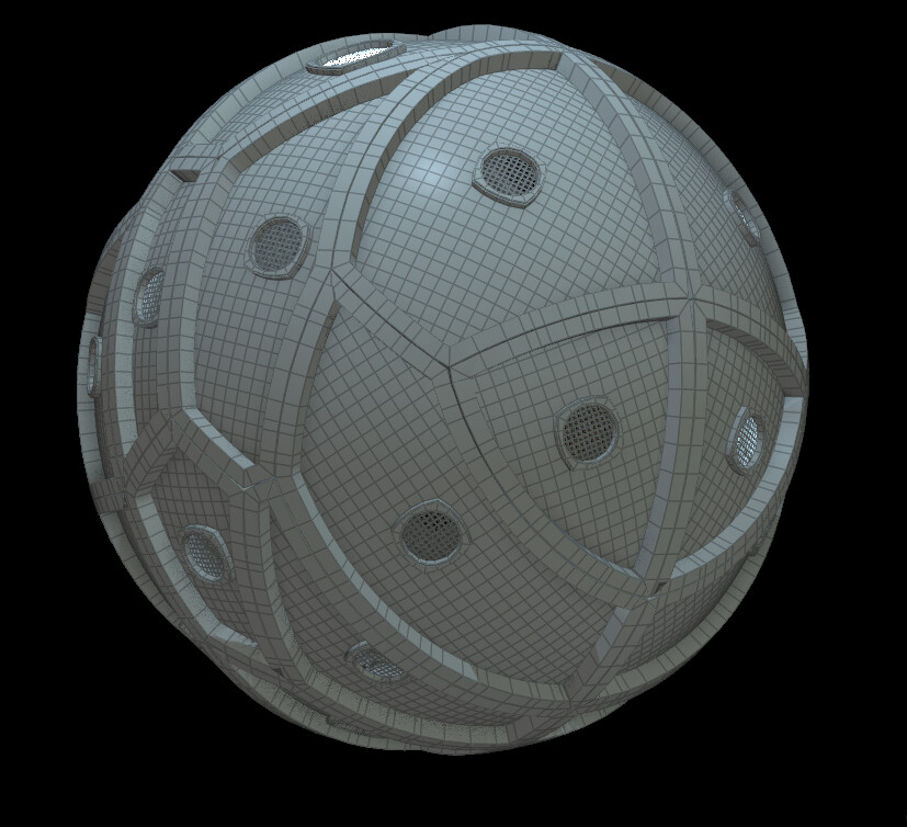
Here is an example of the system. What I did is I took a sphere did voronio fracturing on it and put it in the system that will create on each piece a pattern or panel that I procedural modeled. You can also see it that I model one small part and it will automatically be applied every where. 

In the image above I start testing on a sphere and when I got a nice result on the sphere, I changed the input to the test geometry and instantly got this result of a sort of sci-fi suit. This sphere was also the first test with the system.

What I'm doing is actually one big for loop. In here I model one procedural panel and the loop is going to do the rest of the work.

The main challenge is how can I create cool patterns and panel on more complex shapes. The solution is that you need to convert your geometry to uv space. This will give you a flat version that is easier to model on then a shape that is more deformed.

So the general workflow of this is that you unwrap it, then force the geometry into the uv space. With this shape it is easier to model on and then convert it back in its original shape.


Geometry (world space) to uv space

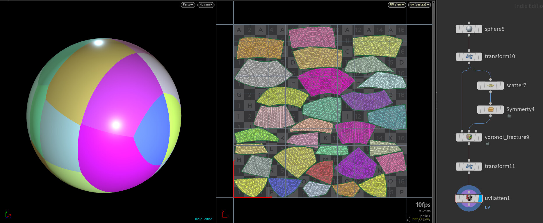
To get a similar system I can recommend you starting with a sphere and do fracturing on it (more about voronio fracturing in blog10). You should keep the amount of piece low so it is fast to see results, like 30 piece. 

This is my setup, feel free to use modify it but for testing this is just fine.


Once you have the setup you can create for-each named primitive. This will go over each piece that is created by the voronoi fracture.

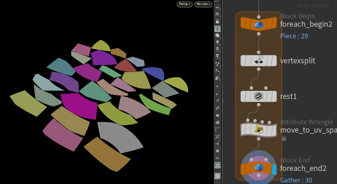
To move geometry to uv space in the viewport you will have to do a few things. First use vertex split node and fill in uv as attribute, so it splits based on the uv. Also enable promote to Point attribute, this will put the uv information in the point attribute and you will need it later.

Next is placing down a rest node, this is going to create a new attribute and will copy the position attribute. Like you can see in the picture.

To finally move the geometry into uv space, you can do this with a point wrangle node. You simply going to overwrite the current position of the point with the uv position.

v@P.x = v@uv.x;
v@P.z = v@uv.y;
v@P.y = 0;

Which should look like this. And with this result it will be nicer to work with.


uv space back to world space

With one wrangle you can but the geometry back in the original form. In the image you can see that I used the Polyexpand 2D visualize it and see if the system is working.

In the wrangle you can use the following. You create first some attributes to store the information. Then using the xyzdist function, this finds the distance from the origin to the closest point on the geometry, and also outputs the primitive number and UV coordinates for the closest point that you will need to use in the next line. With primuv you can interpolate the value of rest at a certain parametric position which is calculated in the xyzdist.

int posprim;
vector param_uv;
float maxdist = 10;
float dist = xyzdist(1,@P,posprim,param_uv,maxdist);
vector pos = primuv(1,"rest",posprim,param_uv);
v@P = pos;

Once you have done this, the geometry should have now its original form back. If you would like to see another example, I can recommend you installing the game dev tools and in there look for the SciFi Panels. In that node it works with the same system and gives you a good idea what it can do.


Modelling and Current limitations

As I mentioned before certain modelling operations are going to be easier on a flat shape. 

A few images above I used the Polyexpand 2D, when using it works way better on a shape that is flat then a complex model. And there are more of these situations where modelling and certain nodes working better on the flat shapes. 

During this modelling stage a tool got my attention, it is made Gary Hanna and is called Circle TopoBool. You can get it for free and watch the videos of it. The tool will make a perfect circle in the geometry, with as input a bounding box of where you would like the circle. 

Here is an example using it in the system. All the "vents" are made thanks to that tool. Combining it with some extrudes and you will get something similar.

If you want something like in the picture, you have to know that some adjustments might not translate if convert back from uv to original shape. In the last wrangle you force the shapes to match the original back but if you did an extrude before it will loses its shape. In the picture below show what I mean.

This is the current limitation of the system. Paul from SideFX mention that the detail mesh sop solves this issue. So far I looked into the detail mesh sop but have not found something that is stable enough to share.

In conclusion I like this way of working, it can feel really powerful when you model only 1 panel and the systems builds the rest for you.


Thank you for taking the time to take a look at the blog and see you next week. :)

Houdini Blog #14: COP Part 2

General / 03 June 2019


UPDATE: I made a video about this https://www.youtube.com/watch?v=HtCxq8UZGD4


This week will continue more on the COP’s in Houdini. If you would have missed post number 13 here is a link. What I want to explore now is how you can use geometry and get that information into COP’s or textures.

As last post Sander Meij mentioned that the benefit of COP’s over Substance Designer can be the link with geometry. I watched this video to get an idea on how you can create a link between your geometry and the COP’s.


A small exercise I made with this is a system were a simple simulation is happening and that data is converted into a height map. 

If you are experienced with Substance Designer, you know that it is not easy to create overlapping or layering like debris.

With this system the height map is in real-time calculated in COP’s and with one press it is saved and opened to Substance Designer.

Here is an example.

Real time result

Export and opening the height map in Designer with one click

SOP import

First thing to talk about is the SOP import node. This COP node can convert the input to a texture. The input of this node has to be a 2d volume, so just giving it polygons it won’t work. The geometry has to be converted to a 2d volume to be usable for the SOP import node.

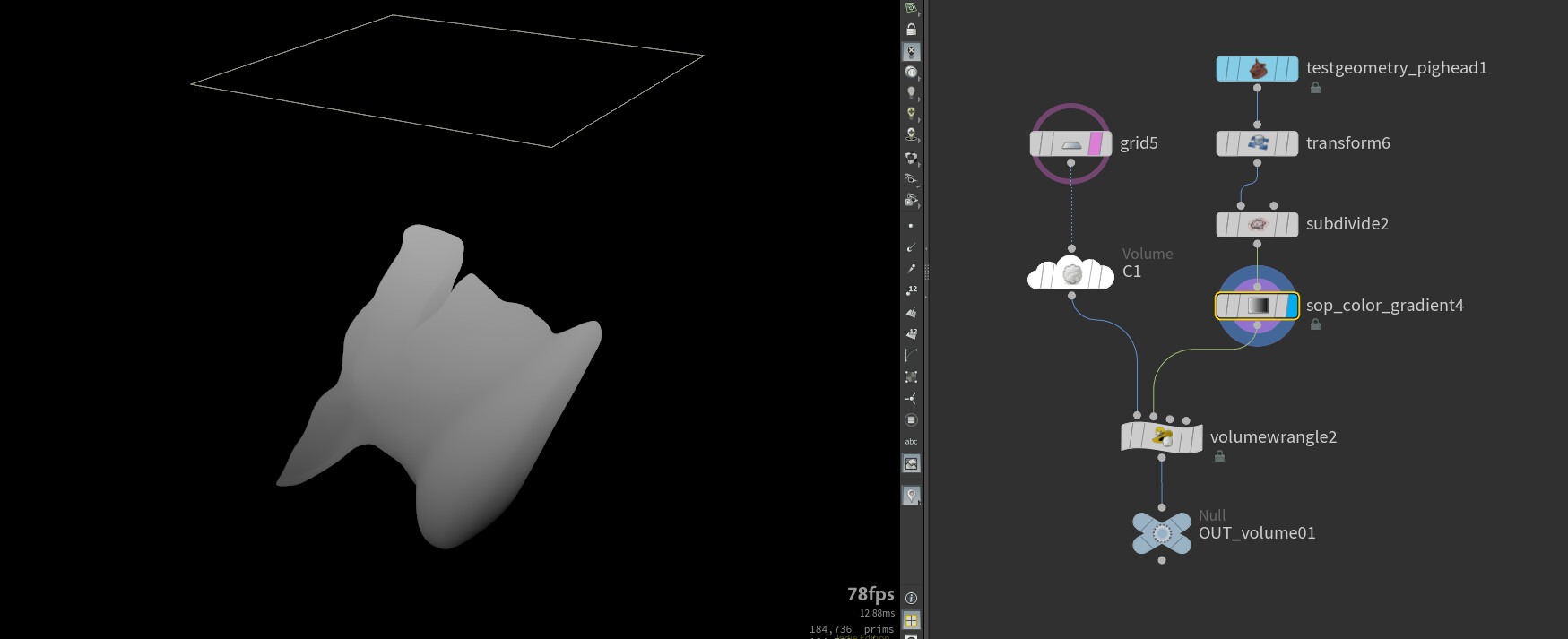
For testing you can make a model or use the test geometry of Houdini. Then you will need a grid this represents the texture space. Everything in the grid, looking from topview, will be in the texture. The grid is also been placed 10 units high.

From this grid a volume will be created, you could do this with the volume SOP. In the Volume SOP there will be settings to be adjusted. First you will need to set it to vector with this you can save color ( or 3 value/floats). Then give it a name like C and enable “two dimensional”.

The settings at the bottom are used for the quality of the volume. Set the uniform sampling to non-square, this way you can set the quality of each axis. In this example I will use 1024, the higher the number the more time it will need to calculate the result. Also you don’t need to set a resolution in the Y because it is the global up axis and you have a 2d volume.

At this point you might not see the volume that is because you have not assigned any values to the volume. If in the initial value you add a number in there the volume should have a color now.


Next step you will have to create a gradient on your model. In the game dev tools there is a node for this. So you don't have to create it your self.

When applying on a model you will have a result like this. You could also add a subdivide or voxel it, to get better quality.

In the wrangle in the picture the information is being transferred into the volume.

In the wrangle there is VEX code (this was also show in the video I mentioned at the beginning.) Pay attention to naming v@C is your volume that you have created. The C is the name of the volume.

vector hitPos;
float hitU;
float hitV;

int hitPrim = intersect(1 , @P , set(0,-100,0), hitPos, hitU, hitV);
int hitPoint = primpoint(1, hitPrim, 0);

if (hitPrim != -1)
{
   v@C = point(1, "Cd" , hitPoint);
}

Once this is al setup up put a null node down and reference this to the import SOP in the COP netwerk.

If everything went good you have a result like this in the composite view.


Simulation to height map

To have a simulation to a height map is the same setup. Instead of having the pighead as model you link your DOP import SOP to the gradient.

By making a simulation in Houdini you can get a nice overlapping and layering height map. In Designer it is not that easy to do layering with out intersecting into other shapes.

If the you work with a volume and polycount that is low enough the height map will be in real-time :o

One small trick here, is what if you want to make it tillable. With the game dev tools there is also a node that can do that for you. The node to use is called mesh tiler.

For exporting the ROP output file is used in the COP network. With this you can save to a png and open it in Designer. You can export multiple maps that each contain useful information that can be used in Designer like random gray scale for each brick.

Thanks for taking a look at the blog!

See you next week, I think next post will be interesting.

And feel free to share feedback and thoughts.