
This post will continue on the city generation. As I have the base of the building generation, next part will be placing buildings around.
The buildings will be pre-baked so the tools work a bit faster when placing around the buildings.
The ground plane.
The buildings will be placed based on an image. A good example of this method can be found here.
The node that can handle an image and convert it to geometry is Trace SOP. You can reference an image (in this case a top few of a city layout) and it will trace the image based on black and white values. In the filter settings of the Trace SOP you can do some clean up of the shape. But sometimes you will have to do a clean up with a fuse and the facet nodes. In the facet node you can use the remove inline points. This can remove points that are not really adding detail to a shape.
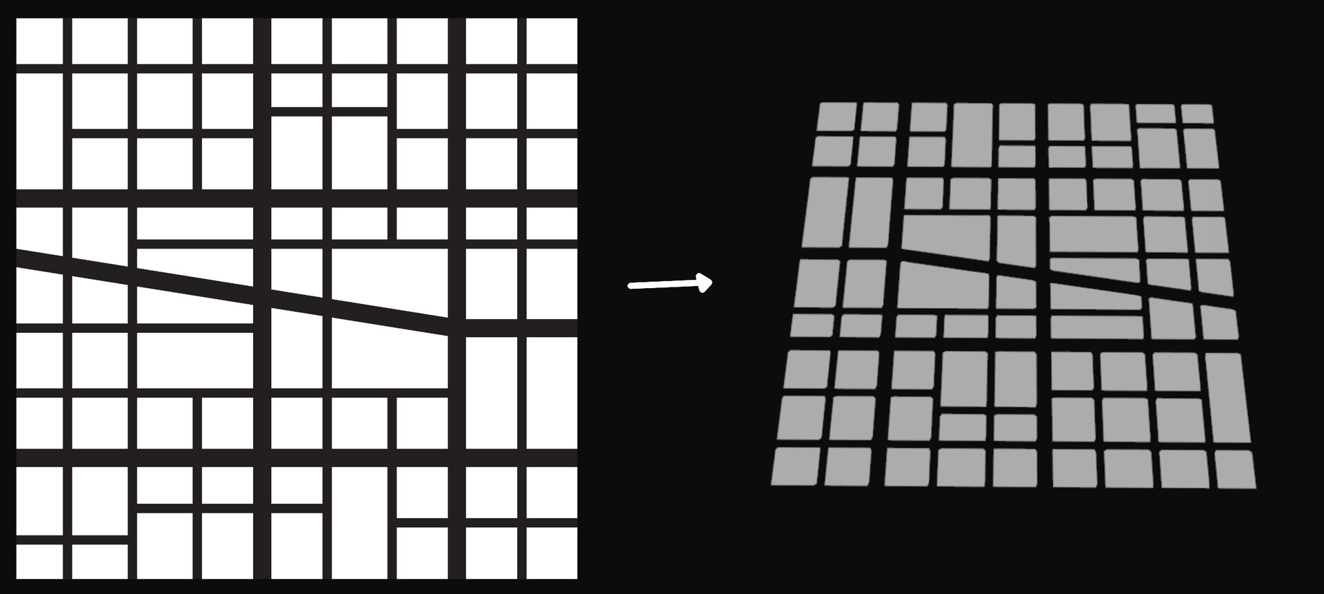
Photo above is example of an image turned into geometry.
This is then the layout that I want for my buildings. You can do an extrude to make buildings/boxes from these. What could be cool is that every building has a different height and that the building is the center are bigger.
To make the variation, you can use the color attribute to save the information. With an attribute transfer it is possible then to convert colors. In the image below you can see that the sphere is transferring a white color into the layout. If you move the sphere the colors will also change.

This is then the blockout for the city by using the Cd value in the extrude node.

Placing buildings
Next step is then replacing the blockout shapes with the buildings that I generated in last post. Since I want to instance the buildings I have to be careful not to break the instancing. Using instancing of buildings will save some performance and it will also be nicer to work with the tool as it will work faster.
First then that you can do is getting the middle point of the buildings. This point is then used to copy buildings on. An easy way of getting that middle point is by using a for-each connect piece loop. This will loop over all the building one by one. In the loop use a fuse and because it will snap on average it will go to the middle. (Also disable Remove repeated vertices)
The result should look like this.

With these new created points you can store the bounding box size of the blockout buildings.
You can do this with a wrangle node. The first input is the point and the second input of the wrangle is the blockout shape. This wrangle is also in the for-each loop.
@scale = getbbox_size(1);
By saving the values in the @scale Houdini will know what to do with this attribute when you use a copy to points node.
This should be the result when you copy to points a model.
